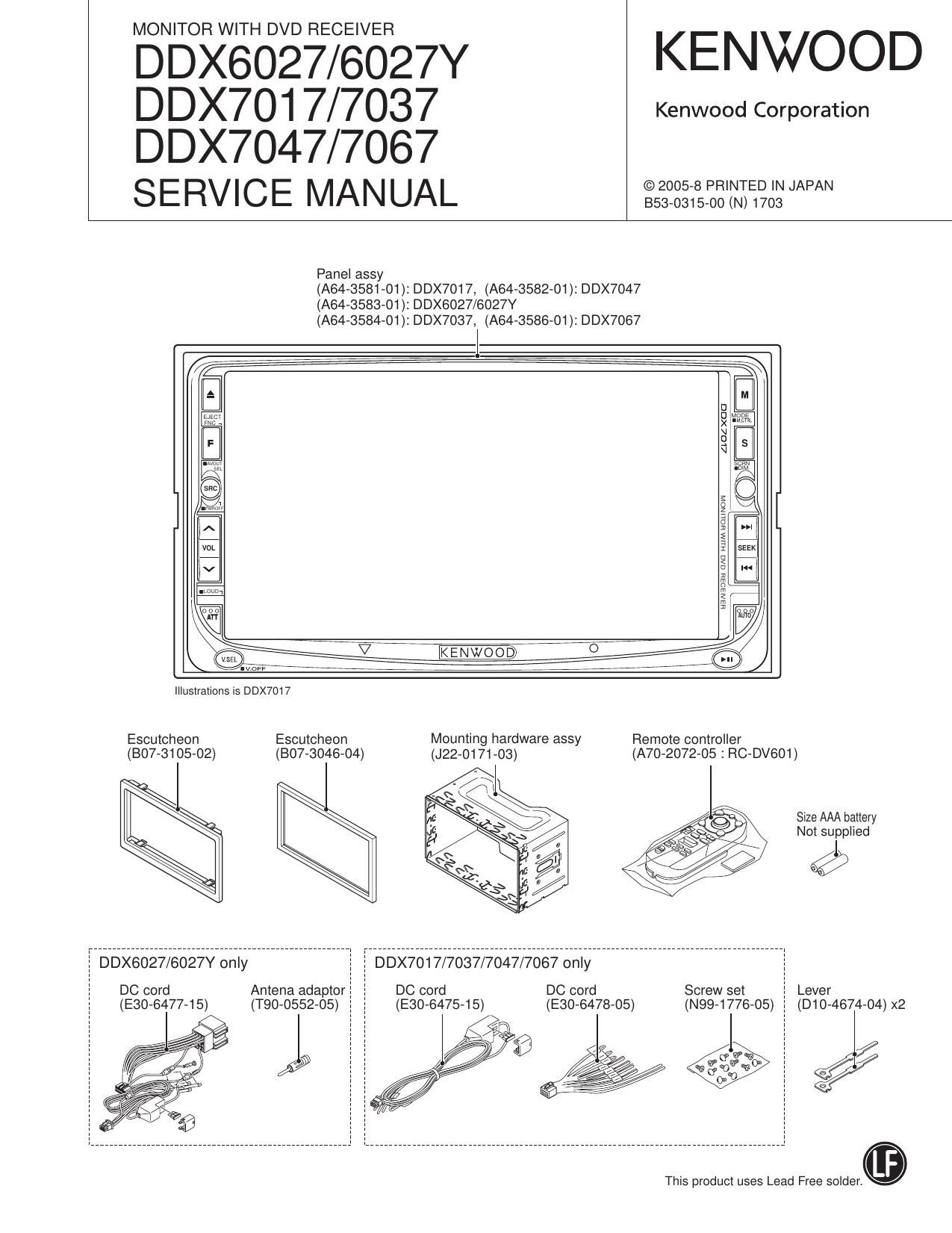
Kenwood DDX 6027 HU Service Manual

This is the 100 pages manual for Kenwood DDX 6027 HU Service Manual.
Read or download the pdf for free. If you want to contribute, please mail your pdfs to info@audioservicemanuals.com.

Page: 1 / 100
left right
Kenwood DDX 6027 HU Service Manual

Extracted text from Kenwood DDX 6027 HU Service Manual (Ocr-read)


Page 2

DDX6027/6027Y/7017
DDX7037/7047/7067

NOTES ON ASSEMBLING THE MECHANISM

1. Fasten Screw A so that the interval (a) will be about 5.2mm
and the interval (b) will be about 2.6mm (The interval (a)
can be measured using a pair of vernier calipers or similar
tools.)

2. Turn B so that Position (0) will come at about the center of
interval (d).

3. Then, play the test disc and fine tune A or B so that the jitter
value would be minimized.

Page 15

DDX6027/6027Y/7017
DDX7037/7047/7067

MICROCOMPUTERS TERMINAL DESCRIPTION

Pin No. Pin Name Module (physical) l/O Application Processing Operation Description
36 SCUCHROMAfiSCL Chroma y l/O Access with chroma 7 IC
37 BEiRST B/E O B/E circuit reset L: RESET
38 POWERiDET Power supply I 8.5V over current detection H: Abnormality detection
39 BLiDET INVERTER l Backlight abnormality detection H: Abnormality detection
4O BiPON Power supply 0 SW14 (BU SW)ON/OFF control H: ON
41 ,42 NC 0
43 FSEL1 Power supply 0 DC-DC IC oscillation trequency switching
44 FSEL2 Power supply 0 DC-DC IC oscillation trequency switching
45 FSELSW Power supply 0 Control at DC-DC IC FSEL switching Normal: H, At FSEL switching: L
46 PON Power supply 0 Power supply ON/OFF control H: ON
47 MCNT Power supply 0 Motordriver voltage switching (MECHA7V) (tDlN) H: 7V, L: SV
48 RGBisW VIDEO 0 RGB signal switching L: DVD, H: OTHER
49 OSD7CS OSD O OSD-IC chip select (OSD)
5O OSDiDATA OSD 0 Data output to OSD-IC (OSD)
51 OSD7CLK OSD O Clock output to OSD-IC (OSD)
52 OSDiRST OSD O Resetting OSD-IC (OSD)
53 WRT7E2P pCOM | Used for E2P writing

PWM output.
54 POWERiPWM Power supply 0 DC/DC-IC oscillation trequency control

At FSEL switching stopped. (Output L)
55 JlGiEJ EXTRA | 2D|N
56 PWM INVERTER 0 Liquid crystal brightness control
57 STATUSO JIG O For monitor mechanism endurance Jig
58 STATUS1 JIG O For monitor mechanism endurance Jig
59 PANELiDET PANEL | Front panel attach/detach detection H: Detached, L: Attached 2D|N L-fixed
6O STATUS2 JIG O For monitor mechanism endurance Jig
61 SHiMDATA SH-S 0 Data output to SH-3 p-com (GRAPHIC)
62 SHisDATA SH-3 | Data input from SH-3 p-com (GRAPHIC) OSD is output
63,64 NC 0
65 SYSisREO BOX | Request trom BOX p-com
66 SYSiMREQ BOX 0 Request to BOX p-com
67 SYSioN BOX 0 BOX p-com ON/OFF control H: ON, L: OFF
68 SYSisDATA BOX | Data input from BOX p-com
69 SYSiMDATA BOX 0 Data output to BOX p-com
70 SYSiCLK BOX 0 Communication clock with BOX p-com 250kHz
71 MlNLCS/MINLCS PANEL 0 Communication with mini liquid crystal
71 MlNLCS/FLASl-LSDATA pCOM | For Ilash writing
72 MlNliMDATA/MINLMDATA PANEL 0 Communication with mini liquid crystal
72 MlNliMDATAlSUBLEDisw PANEL 0 Model without mini liquid crystal LED ON/OFF HI: ON
72 MlNliMDAWFLASHiMDATA pCOM O For tlash writing
73 MlNLCLK/MINLCLK PANEL 0 Communication with mini liquid crystal
73 MlNLCLK/FLASHicLK pCOM | For flash writing

15

Page 24

DDX6027/6027Y/7017
DDX7037/7047/7067

MICROCOMPUTERS TERMINAL DESCRIPTION

24

Pin No. Pin Name l/O Application Pin No. Pin Name l/O Application

94 AVSSC - VSS for analog 137 NlOFlD l ATAPI host read signal input

95 PLFLT2 l Condenser 2 for PLL 138 IOFlDY 0 Ready output to ATAPI host

96 PLFLT1 l Condenser 1 for PLL 139 NDMACK l ATAPI host DMA acknowledge input

97 AVSSB - VSS for analog 140 INTRQ O Interruption output to ATAPI host

98 ARE l Equivalent RF+ input 141 NIOCS16 0 Not used

99 NARF l Equivalent FlF- input 142 DA1 l ATAPI host address signal input

100 VHALF | Reference voltage 1.65V input 143 NPDIAG | Diagnosis from ATAPI slave to master
VREFH register for reference 144 DAO l ATAPI host address signal input

101 HV I current power supply 145 VSS - VSS

102 VREFH l Reference voltage 2.2V input 146 VDD3 - VDD (3.3V)

103 DSLF2 l Condenser 2 for DSL 147 DA2 l ATAPI host address signal input

104 DSLF1 l Condenser 1 for DSL 148 NCSfFX l ATAPI host chip select signal input

105 AVDDB - VDD (3.3V) for analog 149 NCS3FX l ATAPI host chip select signal input

106 JITOUT O For jitter monitor 150 NDASP O ATAPI drive active/slave

107 AVDDA - VDD (3.3V) for analog 151 HDD15 l/O ATAPI data input/output

108 TECAPA | Not used 152 HDDO l/O ATAPI data input/output

109 ADO (FE) l FE input 153 HDD14 l/O ATAPI data input/output

11o AD2 (AS) I As input 154 HDD1 l/O ATAPI data input/output

111 AD1 (TE) l TEph/TE3b input 155 HDD13 l/O ATAPI data input/output

112 AD3 (ENV) I RF envelop input 156 voos - VDD (3.3V)

113 AD4 (RFDIFO) l Push-pull TE input 157 VDD15 - VDD (1.5V)

114 AD5 l Focus drive AD input 158 VSS - VSS

115 ADS l Tracking drive AD input 159 HDD2 l/O ATAPI data input/output

116 AD7 (IOP) l Laser diode current measurement 160 HDD12 l/O ATAPI data input/output

117 ADE (TEMPiDET) l Temperature monitoring input 161 HDD3 l/O ATAPI data input/output

118 AVSSA - VSS for analog 162 HDD11 l/O ATAPI data input/output

119 PWMO (FOD) 0 Focus drive output 163 HDD4 l/O ATAPI data input/output

120 PWM1 (TRD) 0 Tracking drive output 164 HDD10 l/O ATAPI data input/output

121 VSS - VSS 165 HDD5 l/O ATAPI data input/output

122 VDD3 - VDD (3.3V) 166 VSS - VSS

123 IDGT 0 Not used 167 VDD3 - VDD (3.3V)

124 DTRD 0 Not used 168 HDD9 l/O ATAPI data input/output

125 MONIO 0 Internal monitor signal 169 HDD6 l/O ATAPI data input/output

126~130 MON|1~5 0 Internal monitor signal 170 HDD8 l/O ATAPI data input/output

131 SW72¥3 l 80m E)-STOP, Lo-START detection 171 HDD7 l/O ATAPI data input/output

132 SW71X5 l 12cm Ei-STOP detection 172 VDDH - 5V reference power supply

133 DMARQ 0 DMA request output ATAPI host 173 NRESET l ATAPI reset signal input

134 NIOWR l ATAPI host write signal input 174 MASTER l ATAPI master/slave signal input

135 VDD3 - VDD (3.3V) 175 SCL O EEPFlOM clock output

136 VSS - VSS 176 SDA l/O EEPFlOM data inputJoutput