Kenwood DDX 512 HU Service Manual

This is the 86 pages manual for Kenwood DDX 512 HU Service Manual.
Read or download the pdf for free. If you want to contribute, please mail your pdfs to info@audioservicemanuals.com.

Page: 1 / 86
left right
Kenwood DDX 512 HU Service Manual

Extracted text from Kenwood DDX 512 HU Service Manual (Ocr-read)


Page 1

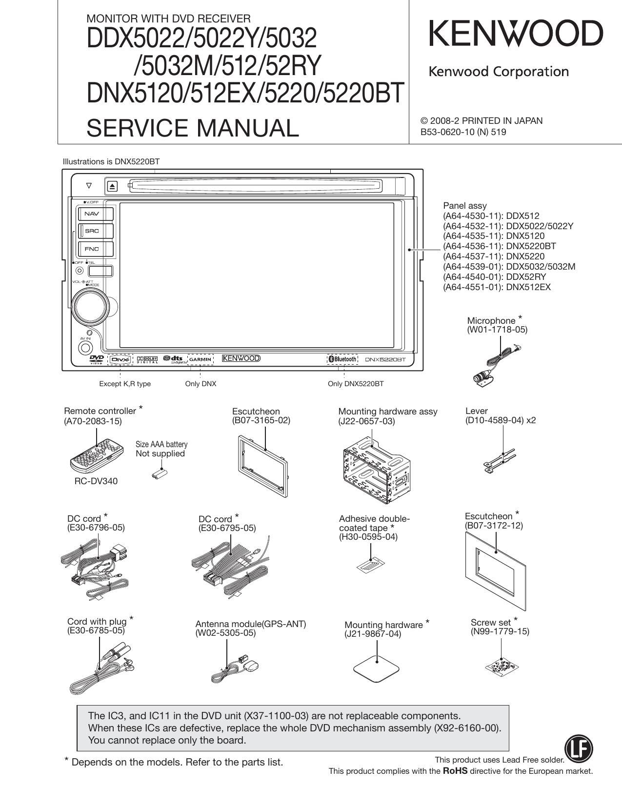
MONITOR WITH DVD RECEIVER

DDX5022/5022Y/5032 KENWOOD

/5032M/512/52RY Kenwood Corporation
DNX5I20/512EX/5220/52208T

SERVICE MANUAL sszNgzgifiz'tiiegNNNN

Illustrations is DNX522OBT

N [E fleeiiii i 7 iiiifij 7
"W Panel assy
[i AV l (AM-453041): DDX512
EH SEC (AM-453241): DDX5022/5022Y
(A64-4535-11): DNX5120
we (AM-453641): DNX5220BT
(A64-4537-11): DNX5220

n@ i[ ii (A64-4539»01): DDX5032/5032M
(A64-4540»01): DDX52RY
(A64-4551»01): DNX512EX

Microphone *
(W01-1718-05)

Jgp ammiftwil 9915211101111 owxeaaom)
1 1
Except K,Fl type Only'DNX Only'DNX5220BT

Remote controller * Escutcheon Mounting hardware assy Lever
(A70-2083-15) (BO7-3165-02) (J22-0657-03) (D10-4589-04) x2

Size AAA battery

Not sulpplied %/

RC-DV340 W

DC cord * DC cord * Adhesive double- Escutcheon *

(E30-6796-05) (E30-6795-05) coated tape * (307-3172-12)
, (H30-0595-04) J

Cord with plug * Antenna module(GPS-ANT) Mountin hardware * Screw set *
(E30-6785-05) (W02-5305-05) (J21_98§7_04) (N99-1779-15)

ee <5 ,.

The IC3, and IC11 in the DVD unit (X37-1100-03) are not replaceable components.
When these le are defective, replace the whole DVD mechanism assembly (X92-6160-00).

You cannot replace only the board.
This product uses Lead Free solder.

* Depends on the models. Refer to the parts list.
This product complies with the ROHS directive for the European market.

Page 16

DDX5022/5022Y/5032/5032M/5l2/52RY
DNX5120/512EX/5220/52208T

TEST MODE

1 Operations

The system can be transferred to the Test mode with the

following two approaches:

(D DNX/DDX: [SRC] key+[A|'|'] key
KVT : [OPEN] key+[SRC] key
While keep pressing the above key, press [Reset] key to
start the system.

(2) in the standby source mode while the system is in the
ON condition (in the normal condition), enter 2 4 Seek
Up a 3" with (SW: AUD) of the remote controller.

Turn the system OFF in 30 minutes when it is started in the
Test mode.

Do not display the Opening screen when the system is
started in the Test mode.

2 Screen transition

The system is started with the Test Mode Main screen when
it is started in the Test mode. When the system is trans-
ferred to the Test mode using the remote controller, it trans-
fers to the Test Mode Main screen.

A variety of screens that can be transferred from the Test
Mode Main screen is shown in Figure 2.

Refer to Section 3 for the functions in each screen.

3 Specification of screens
This section describes the Test mode functions available in
each screen.

3.1 Test Mode Main screen

This section describes the keys that can be used to transfer
to each screen.

Contents of the display shown in the Test Mode Main
screen are described in Figure 3.1.

Test Mode Main

information Touch Auto Adjust
Sen/ice HPOSI Inverter
Direct Select iPod NAVl Bluetoath

Figure 3.1 Test Mode Main screen

K

Test Mode Main
information Serwce Direct Select Touch HPOSI iPod Auto Adjust Inverter NAVi Bluetooth
. Scuroe . .
Serial/Tuner . IPod Auto Adiust Inverter
etc 355%" m Adm Gaphc Cemlication Start High/LOW
p
EZPROM NAV ezpaom EZPROM
Write Write Write
EZPROM
Write

Figure 2 Screen transition

Page 19

DDX5022/5022Y/5032/5032M/5l 2/52RY

DNX5I20/512EX/5220/52208T

TEST MODE

Frequency : Default value of the set
Note that the frequency remains unchanged after exiting

from the Setup screen at the completion of the setup.

3.7 Direct Select screen

Transfer to the Direct Select screen. Source Direct screen
shall have the screen that has 9 keys. Audio Control/Setup
shall be done in the same manner as in the normal screen
transfer.

3.8 Touch screen

Fine-tune the variations of touch feeling in of each set.
Touch 4 markers one by one, and the adjustment is com-
pleted when the Write OK is shown on the screen.

If the Write NG" is shown, transfer to the Test mode again
to re-start the adjustment from the first step.

The Touch Adjustment screen is shown in Figure 3.8.

Touch Adjust Touch Adjust
trpoinl being input eroinl being input
Ci) Wite OK/NG

arpoint being input Arpoinl being input

+i~ a}

Figure 3.8 TOUCH screen

Key Specification

Cancel: When the Cancel button is pressed while enter-
ing the 1st point, the system transfers to the Test
Mode Main screen.
When the Cancel button is pressed while enter-
ing the other point than the 2nd point, the system
transfers to the status to enter the 1st point.

Return : Transfer to Test Mode Main screen

3.9 HPOSI screen

Adjust horizontal position of each screen.

The screen shall be transferred like; Graphic->NAVI.
Graphic and NAVl of DNX are used in the adjustment of Dot
FREQ/Phase. The Adjustment screen is shown in Figure 3.9.

HPOSlAdjust
Gap,
(NAV') HPOSI
Stepvaiue
Dot FREQ C9
stepvaiue

Dot Phase
Step value

Figure 3.9 HPOSI screen

HPOSI Adjust

HPOSI OK/NG

Key Specification

Next : Transfer to the next HPOSI Adjustment screen.
When the screen is NAVI, the screen starts writing
in the E2PROM.

<< : Screen toward the left.

>> : Screen toward the right.

Cancel: Transfer to Test Mode Main screen

Return : Transfer to Test Mode Main screen

If HPOSI NG (E2PROM Write N6) is shown, transfer to the
Test Mode again to start over the adjustment.

3.10 iPod screen
Check communication for iPod authentication.
The iPod screen is shown in Figure 3.10.

iPod Check iPod Check

iPod OK/NG

c>

Figure 3.10 iPod screen

Key Specification
iPod Check :Start checking communication for iPod
authentication.
Cancel, Return: Transfer to Test Mode Main screen

19

Page 63

DDX5022/5022Y/5032/5032M/5l 2/52RY
DNX5I20/512EX/5220/52208T
EXPLODED VIEW (PANEL MECHANISM)

SIZE AAA BATTERY
5 (NOT SUPPLlED)

//
/ ,
%/

D $2.6x6 : N78-2660-48
F M2X3 : N35-2003-48
G ¢2X8 : N80-2008-43

->:<- Depends on the models. Refer to the pans list.

Parts with the exploded numbers larger than 700 are not supplied. 63