Kenwood DDX 5034 HU Service Manual

This is the 72 pages manual for Kenwood DDX 5034 HU Service Manual.
Read or download the pdf for free. If you want to contribute, please mail your pdfs to info@audioservicemanuals.com.

Page: 1 / 72
left right
Kenwood DDX 5034 HU Service Manual

Extracted text from Kenwood DDX 5034 HU Service Manual (Ocr-read)


Page 1

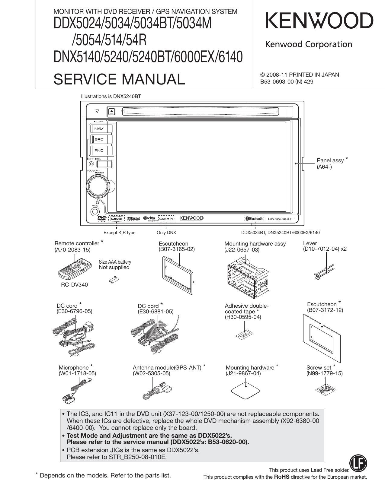
MONITOR WITH DVD RECEIVER / GPS NAVIGATION SYSTEM

DDX5024/5034/5034BT/5034M KENWOOD
/5054/514/54R

DNX5140/5240/524OBT/6000EX/6140
SERVICE MANUAL IIIIIIIIIIIIWN

Kenwood Corporation

Illustrations is DNX524OBT

[I NAV

EI

FNC

] E:E

WM?

:Balueiaam: DNXEEADET

ExcepI KB type OnlleNX DDXSOISABT, DNX524OBT/6000EX/6140
Remote controller * Escutcheon Mounting hardware assy Lever
(A70-2083-15) (BO7-3165-02) (J22-0657-03) (D10 7012- 04)x
Size AAA battery I -

a / Not supplied

l
RC-DV340 9
DC cord * DC cord * Adhesive double- Escutcheon *
(E30-6796-05) (E30-6881-05) coated tape * (807-31 72-1 2)

(H30-0595»04) I

Microphone * Antenna module(GPS-ANT) * Mounting hardware * Screw set *
(WO1-1718-05) (W02-5305-05) (J21 -9867-04) (N99-1779-15)

EEE <1> E

0 The IC3, and |C11 in the DVD unit (X37-123-00/1250-00) are not replaceable components.
When these le are defective, replace the whole DVD mechanism assembly (X92-6380-00
/6400-OO). You cannot replace only the board.

- Test Mode and Adjustment are the same as DDX5022s.
Please refer to the service manual (DDX5022s: 353-0620-00).

- PCB extension Jle is the same as DDX5022s.

Please refer to STR_B250-08-01 OE.
This product uses Lead Free solder.

* .
Depends on the mOdeIS- Refer to the parts I'St- This product complies with the ROHS directive for the European market.

Page 10

DDX5024/5034/5034BT/5034M/5054/514/54R
DNX5140/5240/524OBT/6000EX/614O

MICROCOMPUTERS TERMINAL DESCRIPTION

10

O SYSTEM MICROCOMPUTER 30878MJBA31GP (X34-575: IC104)

Pin No. Pin Name IIO Application Processing / Operation / Description
1 EVOLisDA/EVOLisDA I/O Communication data with E-VOL
1 EVOL,SDA/E2P,SDA 0 Communication data with E2P
2 TV7MCLREQ 0 Request to TV u-com
2 NC 0 Output from mode) Without TV is fixed to L
3 TV,SC,CON 0 Request to start TV u-com
3 NC 0 Output from mode) Without TV is fixed to L
4 VSYNciDET | Video external input detection Detects if there is VSYNC signal or not
5 VOL+ | Detects VOL key Detects pulse Width
15 pulses/360°, 2 clicks, 1 pulse

6 VOL_ I Detects VOL key |I):tréjiiltsSeIs)256:)Siwgficiicks, 2 pulse
7 HSY 1 HD input Counts HD
8 VD I VD (VSYNC) input
9 SRC I Source key
10 TV,SC,REQ | Request from TV u-com
10 NC 0 Output from model without TV IS fixed to L
11 REVERSE | Reverse detection L: Detection, H: Normal
12 PWICisTBY 0 Power IC standby H: ON, L: OFF
13 INV7PWM O Inverter frequency control (Output by timer)
14 PWICiMUTE 0 Power IC output mute control H: OFF, L: ON
15 BYTE
16 CNVSS
17 XCIN
18 XCOUT
19 RESET
20 XOUT
21 V88
22 XIN
23 VCC1
24 NMI
25 ACC,DET | ACC detection H: ACC reduced power detection
26 BU7DET | Backup power supply detection H: Backup reduced power detection
27 RicLK | Clock input from RDS decoder
27 NC 0 Output from model without RDS is fixed to L

(To destination X and V)
28 NC 0
29,30 NC 0 Not used Output is fixed to L"
31 PWM 0 LCD brightness control (PWM output) PWM output synchronized with VSY
32 PARKING | Parking detection (For all the destinations) H: Detection, L: When car is running
33 BEEP O BEEP PWM output