Kenwood DDX 5022 HU Service Manual

This is the 86 pages manual for Kenwood DDX 5022 HU Service Manual.
Read or download the pdf for free. If you want to contribute, please mail your pdfs to info@audioservicemanuals.com.

Page: 1 / 86
left right
Kenwood DDX 5022 HU Service Manual

Extracted text from Kenwood DDX 5022 HU Service Manual (Ocr-read)


Page 1

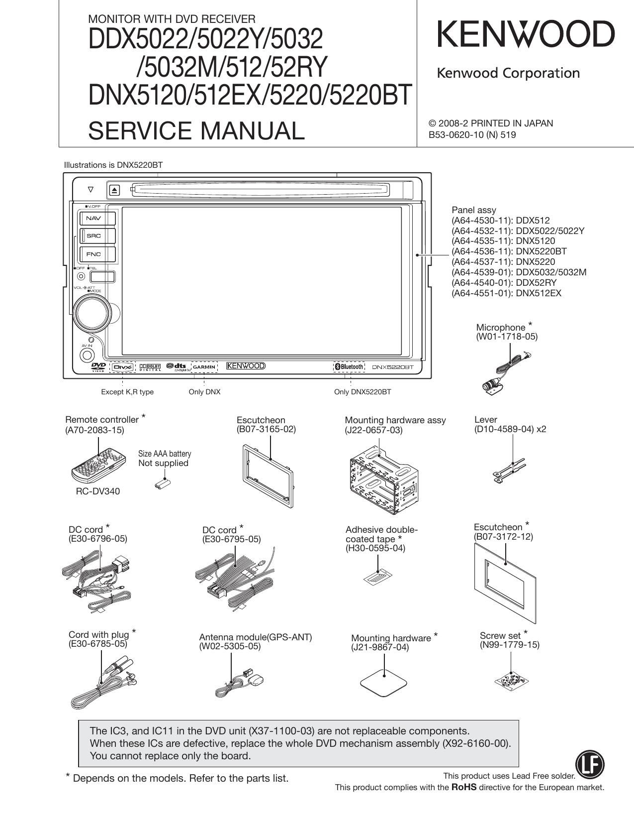
MONITOR WITH DVD RECEIVER

DDX5022/5022Y/5032 KENWOOD

/5032M/512/52RY Kenwood Corporation
DNX5I20/512EX/5220/52208T

SERVICE MANUAL sszNgzgifiz'tiiegNNNN

Illustrations is DNX522OBT

N [E fleeiiii i 7 iiiifij 7
"W Panel assy
[i AV l (AM-453041): DDX512
EH SEC (AM-453241): DDX5022/5022Y
(A64-4535-11): DNX5120
we (AM-453641): DNX5220BT
(A64-4537-11): DNX5220

n@ i[ ii (A64-4539»01): DDX5032/5032M
(A64-4540»01): DDX52RY
(A64-4551»01): DNX512EX

Microphone *
(W01-1718-05)

Jgp ammiftwil 9915211101111 owxeaaom)
1 1
Except K,Fl type Only'DNX Only'DNX5220BT

Remote controller * Escutcheon Mounting hardware assy Lever
(A70-2083-15) (BO7-3165-02) (J22-0657-03) (D10-4589-04) x2

Size AAA battery

Not sulpplied %/

RC-DV340 W

DC cord * DC cord * Adhesive double- Escutcheon *

(E30-6796-05) (E30-6795-05) coated tape * (307-3172-12)
, (H30-0595-04) J

Cord with plug * Antenna module(GPS-ANT) Mountin hardware * Screw set *
(E30-6785-05) (W02-5305-05) (J21_98§7_04) (N99-1779-15)

ee <5 ,.

The IC3, and IC11 in the DVD unit (X37-1100-03) are not replaceable components.
When these le are defective, replace the whole DVD mechanism assembly (X92-6160-00).

You cannot replace only the board.
This product uses Lead Free solder.

* Depends on the models. Refer to the parts list.
This product complies with the ROHS directive for the European market.

Page 18

DDX5022/5022Y/5032/5032M/5l2/52RY
DNX5120/512EX/5220/52208T

18

TEST MODE

3.4 Serial No. Entry screen
Enter the serial code of each set from this screen.
The Serial No. Entry screen is shown in Figure 3.4.

3.5.1 DVS-8000 Adjustment screen
This is to display DVS-8000 Servo Adjustment screen.
Refer to the Mechanism Specification for the detail setup.

Serial Number Input

Serial Number Input

III :9
"III
lIl

Figure 3.4 Serial No. Entry screen

Key Specification
0~9 : 10key used to enter the serial No.
Clear : Clear the serial No. being input.
Cancel: Transfer to Service screen
Enter : Start entering the serial No.
(When the entry is successfully completed, the
Write OK" is shown. When the entry is not suc-
cessfully completed, the Write NG" is shown)
When the Write OK" is shown, use this key to
transfer to the Service screen.
If the Write NG" is shown, transfer to the Test
mode again and repeat the entry from the first

step.

3.5 DVD Service Information screen

This screen is to show DVS-8000 sen/ice information. This
screen is also used to transfer to DVS-8000 Adjustment
screen.

The DVD Service screen is shown in Figure 3.5.

DVSVSODO Service Information

DVSVSDOO Adjust

DVSVBOOO Service Information
"mm...
um...
«mm...

"W' "nun-u
mm- E> ..........
.m... ..........
"mw' uncut-ta
twww "nun-u
twww "nun-u

Figure 3.5 DVD Sen/ice Information screen

Key Specification
DVS-8000 Adjust: Transfer to DVS-SOOO Adjustment screen

Next :Transfer to next DVS-8000 Service In-
formation screen.
Return : Transfer to Test Mode Main screen

ovs-Boon Adjust

®orset Cancel

@Facus Hejgm

ovs-suao Adjust ovs»suoo Adjust

Adjust OK/NG

w

Figure 3.5.1 DVS-8000 Adjustment screen

Key Specification
Offset Cancel: Adjust the offset cancel.

Inner Limit : Adjustment of inner circumference limit
Focus Height : Adjustment of focus height
Adjust Start : Start of adjustment
Return (the First screen) : Transfer to Test Mode Main
screen.
Cancel/Return : Transfer to DVS-8000 Adjust screen (Ini-
tial screen).

3.6 Tuner Mute Level screen
Adjust the Mute Level stored in the E2PROM of the Tuner F/E.
The Tuner Mute Level Setup screen is shown in Figure 3.6.

Tuner Mule Level Tuner Mute Level

- :5 wreck/us
Iwme

Figure 3.6 Tuner Mute Level Setting screen

Key Specification
UP : Mute Level Up
DW : Mute Level Down
lWrite: Press and hold (for 1 seconds or longer) to make
the entry in the E2PROM.
Return : Transfer to Service screen.

* Adjust the Tuner Mute Level under the following condi-
tions. Under the other conditions than the followings, the
Tuner Mute Level cannot be adjusted if the Tuner Mute
Level Setup screen is shown.

The frequency shall have to be set before transferring to
the Setup screen.

Audio Source : Tuner

LOUD : OFF

Volume : StepSO

Page 23

DDX5022/5022Y/5032/5032M/5l 2/52RY

DNX5I20/512EX/5220/52208T

TEST MODE

of the E2PROM are not cleared if the same region code is
written.
Only when the different region code is written, contents of
the E2PROM are not cleared.
Serial No. / Security code / Touch correction / HPOSI
correction / Chroma adjustment
DC Offset information / Memory function / Retailer
mode information / Service information

* Note: Since the above data is cleared (un-defined) when
the E2PROM has been replaced during the service, it is
required to readjust the data in the Test mode.

4.15 Security Code writing-in

0 When entering the Security Code that is defined as a pair
of the serial number of the product (for other destinations
than K/R), use [Security Set Up] key on the Setup screen
to call the Security screen.

0 Only when the Security Code of E2PROM of the product
for other destinations than K/R is blank, [Set] key is shown
and press that key.

0 In the Security Code Writing screen, run the same opera-
tion as when registering Security Code in normal mode,
and press the [Enter] key to start writing.

.+ Note: The Security Code to be entered in the above step
is the set-specific code linked to the serial No.

0 Writing of the code is successfully completed when
Complete" is displayed, and if NG is displayed, the
writing the code is unsuccessfully completed.

* Note: if NG is displayed, transfer to the Test mode again
and repeat the above process from the 1st step.

0 When the Security Code is Blank, the system is turned
OFF in 30 minutes.

* Note: In order to turn Security Off in the product whose
destination is K/R while the Security of that product is
turned On, turn the Security off from the Setup screen,
or use the following steps to turn the Security off on the
Security Code Input screen shown when the system is
turned on: Press Tenkey 5 on the remote controller twice
-> Tenkey 2 four times a Tenkey 7 three times.

4.16 Other

0 Do not operate the Back Up Memory function during the
Test mode.

0 In the Test mode, the color of illumination shall be white.

0 The key illumination is in white but GUI shall be the ini-
tial value, and if the color is changed by the Setup this
change of color is shown together with [GUl/] key.

23