Kenwood DDX 50 R HU Service Manual

This is the 72 pages manual for Kenwood DDX 50 R HU Service Manual.
Read or download the pdf for free. If you want to contribute, please mail your pdfs to info@audioservicemanuals.com.

Page: 1 / 72
left right
Kenwood DDX 50 R HU Service Manual

Extracted text from Kenwood DDX 50 R HU Service Manual (Ocr-read)


Page 1

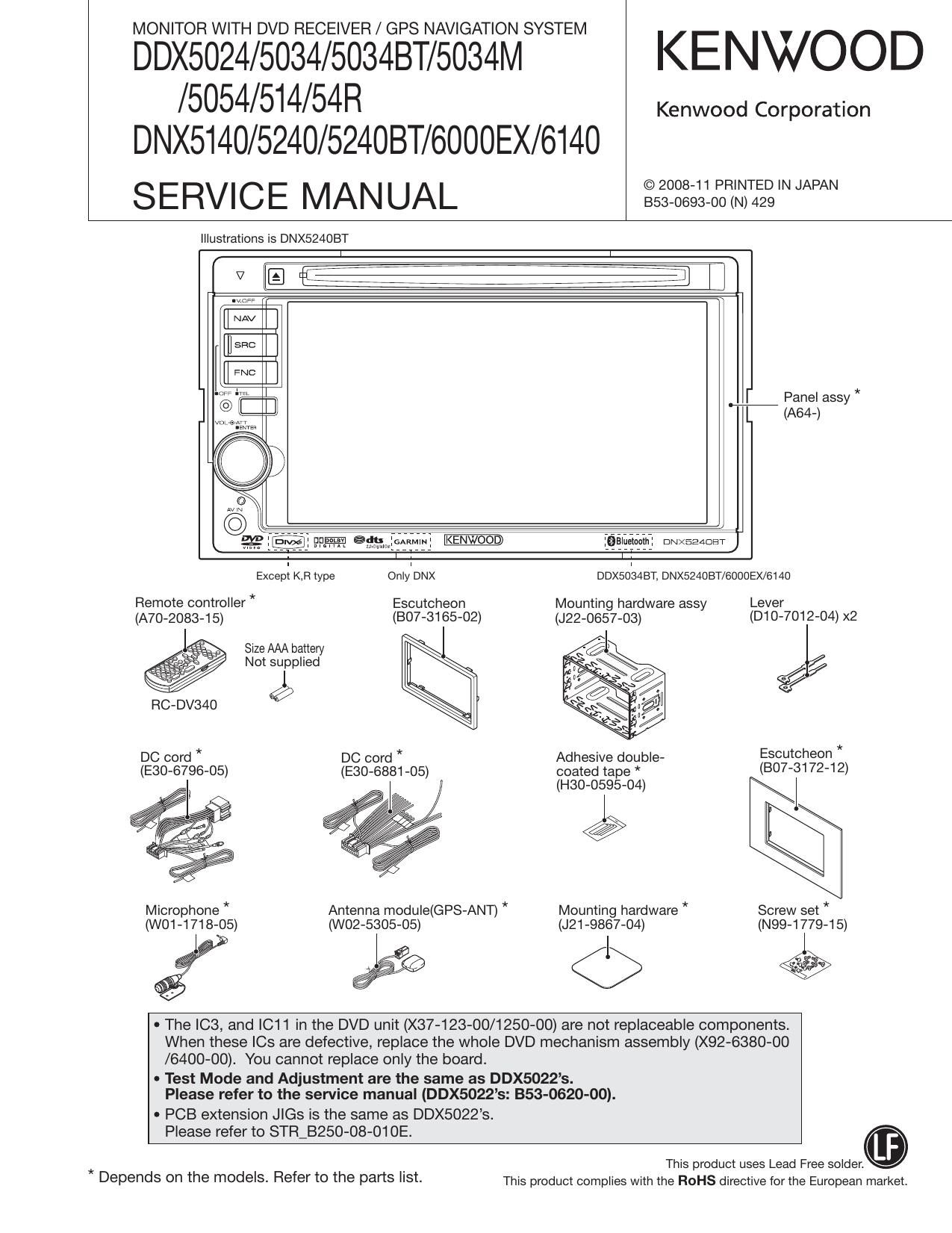
MONITOR WITH DVD RECEIVER / GPS NAVIGATION SYSTEM

DDX5024/5034/5034BT/5034M KENWOOD
/5054/514/54R

DNX5140/5240/524OBT/6000EX/6140
SERVICE MANUAL IIIIIIIIIIIIWN

Kenwood Corporation

Illustrations is DNX524OBT

[I NAV

EI

FNC

] E:E

WM?

:Balueiaam: DNXEEADET

ExcepI KB type OnlleNX DDXSOISABT, DNX524OBT/6000EX/6140
Remote controller * Escutcheon Mounting hardware assy Lever
(A70-2083-15) (BO7-3165-02) (J22-0657-03) (D10 7012- 04)x
Size AAA battery I -

a / Not supplied

l
RC-DV340 9
DC cord * DC cord * Adhesive double- Escutcheon *
(E30-6796-05) (E30-6881-05) coated tape * (807-31 72-1 2)

(H30-0595»04) I

Microphone * Antenna module(GPS-ANT) * Mounting hardware * Screw set *
(WO1-1718-05) (W02-5305-05) (J21 -9867-04) (N99-1779-15)

EEE <1> E

0 The IC3, and |C11 in the DVD unit (X37-123-00/1250-00) are not replaceable components.
When these le are defective, replace the whole DVD mechanism assembly (X92-6380-00
/6400-OO). You cannot replace only the board.

- Test Mode and Adjustment are the same as DDX5022s.
Please refer to the service manual (DDX5022s: 353-0620-00).

- PCB extension Jle is the same as DDX5022s.

Please refer to STR_B250-08-01 OE.
This product uses Lead Free solder.

* .
Depends on the mOdeIS- Refer to the parts I'St- This product complies with the ROHS directive for the European market.

Page 11

DDX5024/5034/5034BT/5034M/5054/514/54R

DNX5140/5240/524OBT/6000 EX/6140

MICROCOMPUTERS TERMINAL DESCRIPTION

Pin No. Pin Name I/O Application Processing / Operation / Description
34 NC 0

35 POWEFLPWM 0 Frequency control of DC-DCJC (CLK output)

36 NAviRX J Communication with navigation system

37 NAVLTX 0 Communication with navigation system

38 TviMCiDATA 0 Data output to TV u-com

38 NC 0 Output from model without TV is fixed to L"

39 VCC1

40 TV,SC,DATA | Data input from TV u-com

40 NC 0 Output from model without TV is fixed to L

41 V83

42 TV,BP,CLK 0 Communication clock with TV u-com

42 NC 0 Output from model without TV is fixed to L"

43 NC 0

44 TUNisDA l/O Communication data with tuner

45 TUNiscL 0 Communication clock with tuner

46 FLDATA 1 DATA input from RDS decoder

46 NC 0 Output from model without BBB is fixed to L"

47 FLQUAL l QUAL input from RDS decoder

47 NC 0 Output from model without BBB is fixed to L"

48~51 NC 0

52 SI O Si control H: ON, L: OFF

53,54 NC 0

55 TYPE3 1 Terminal for destination (ET is required or not) H: With BT, L: Without BT
56 VlLLiR O Brightness control of R in variable illumination Operating frequency: 1kHz
57 V88

58 VlLL,G O Brightness control of G in variable illumination Operating frequency: 1kHz
59 VCCZ

60 VlLLiB O Brightness control of B" in variable illumination Operating frequency: 1kHz
61 KEYilLL O ON/OFF of other illumination than variable illumination H: ON, L: OFF

62 EJECT l Eject key input

63 YO 0 Touch panel control

64 X1 0 Touch panel control

65 NC 0

66 X0 0 Touch panel control

67 INV,SW O Inverter free run frequency switching

68 BLiENA 0 Back light ON/OFF control H: ON, L: OFF

69 VMUTE 0 Video MUTE terminal H: MUTE ON, L: MUTE OFF
70 NTiPAL l NTSC/PAL determination signal input H: NTSC, L: PAL

71 PisTART O DC-DC power supply ON/OFF control

72 PGOOD l DC-DC power supply error detection H: Normal, L: Error

11