Kenwood CV 100 HU Service Manual

This is the 45 pages manual for Kenwood CV 100 HU Service Manual.
Read or download the pdf for free. If you want to contribute, please mail your pdfs to info@audioservicemanuals.com.

Page: 1 / 45
left right
Kenwood CV 100 HU Service Manual

Extracted text from Kenwood CV 100 HU Service Manual (Ocr-read)


Page 1

C-V100(K) 116511er 97115 7:34 PM [I D D 1 /\

865Vi85717AlE50671/L553717ER50 KENWOOD

SERVICE MANUAL

© 1997-6/BSl-5323--00 (K/K) 3676

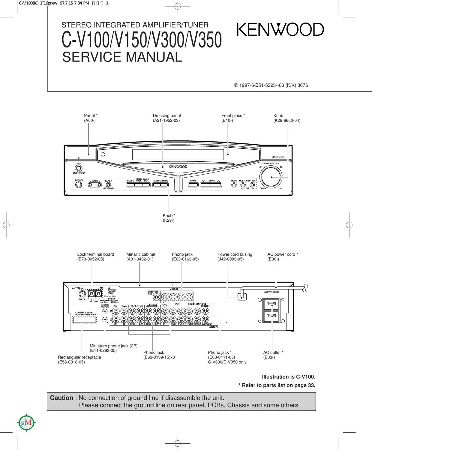
Panel * Dressing panel From glass * Knob
(A60-)

(A21 -1 952-03) (810-) (K29-6660-04)


oursnnnav

""1qu man cmcx u n sn momma

LEE

""""""""""""""""" fi'a'ms'n"""""'
' luummfij

Knob
\ (K29-)
K
Lock terminal board Metallic cabinet Phono jack Power cord busing AC power cord
(E70-0052-05) (A01 (5432-01) (E63-O163-05) (J42-0083-05) (E30-)

WAVE-lg, Emails
"5 "Jan 5%le Amt

small on AUX"__::

mmm _
H O .@ EC?
1: c» @@_ @i@@@ o ::o
L """"" IN IN REC PLAY FRONTSHRROWD SUMMER 7 i
AUDIO
Miniature phone lack (2P)
(E1 1'0293'05) Phono lack Phono jack AC outlet
Rectangular receptacle (E63-0139-15)x3 (E63-O111-05) (E03-)
(E58-OO18-05) C-VSOO/C-V350 only

Illustration is C-V100.
* Refer to parts list on page 33.

Caution : No connection of ground line if disassemble the unit.
Please connect the ground line on rear panel, PCBs, Chassis and some others.

Page 2

c-vmouq 1'16pnew 97.7.15 7:34 PM I] g l] 2

C-VIOO/V150/V300/V35O

CONTENTS /

Contents
CONTENTS / ACCESSORIES
CONTROLS .............................
DISASSEMBLY FOR REPAIR.
BLOCK DIAGRAM .............
CIRCUIT DESCRIPTION
ADJUSTMENT ...................


RE

ACCESSORIES

PC BOARD .............................
SCHEMATIC DIAGRAM .........
EXPLODED VIEW
PARTS LIST ..........
SPECIFICATIONS

'How to reset the microcomputer

The microcomputer may malfunction (impossibility operation,erro-

neous displaertc.) when the power cord is unplugged and plugged

in again while the unit is in ON mode with the Key pressed or due

to other external causesln this case,execute the procedure on the

right to reset the microcomputer and return the unit to the normal
condition.

® Unplug the power cord from the wall outlet.

(3 While pressing and holding the POWER or
(ON/STANDBY)keyIplug the AC cord into the wall out-
let again

- Resetting the microcomputer clears the memory you entered and
returns in to the initial condition when the unit left the factory.

Accessories (C-V100/300)

r
FM indoor antenna(1)
(T90-0809-05): MICX type
(T90-0810-05): KPY type

r
I
I
I
I
I
I
I
I
I
I
I
I
I
I

Graphical Remote Control unit(1)
(C-V300

Batteries(RO3/AAA) (4)
I C V300
(C-V100,only U.S A. and Canada) *

(C-V150/350)

, AM loop antenna(1) (T90-0820-05) 7777777777 1
Loop antenna stand(1)

L ,,,,,,,,,,,,,,,,,,,,,,,,,

(C:V100,only U.S.A. and Canada)

Remote control unit(1) *
(C-V100)
(Except U.S.A. and Canada)

Cable tidy(2)
(F07-0102-04)

IIIau 000030 I:
In): annnaznnu
IUE Lnnnulu, um
/ an: manna r
outon u wanna on
,,,,,,,,,,, A
AC plug adapter (1)

(EO3-O115-05)

4
i Batteries(R6/AA) (2)
(c-v100)

(Except USA. and Cana-
* Use to adapt the plug on

the power cord to the shape
of the wall outlet.(Acoessory
only for regions where use is
necessary)

f
FM indoor antenna(1)
(T90-0809-05). MICX type
(T90-0810-05): ETtype

AM loop antenna(1) (T90-0820-05)

Batteries(R03/AAA) (4)
(-C V350)

Remote control unit(1)
(C-V150)

* Refer to parts list on page 33.

Loop antenna stand(1)

Microphone(1

4v


Graphical Remote Control unit(1) *

Cable tid 2
(c-v350) W I

(F07-0102-04)

ccccccccc 7

I
I
I
I
I
I
I
I
I
1
I
I (Optional with the C-V150)

Batteries(Ft6/AA) (2)

(W01 0935- 05) (C V150)