Kenwood CG 72 Service Manual

This is the 28 pages manual for Kenwood CG 72 Service Manual.
Read or download the pdf for free. If you want to contribute, please mail your pdfs to info@audioservicemanuals.com.

Page: 1 / 28
left right
Kenwood CG 72 Service Manual

Extracted text from Kenwood CG 72 Service Manual (Ocr-read)


Page 1

TUNER/SURROUND PROCESSOR

C-G7/G72

SERVICE MANUAL

KENWOOD

\-
©1996-4/551-5161-00 (K/K) 2771
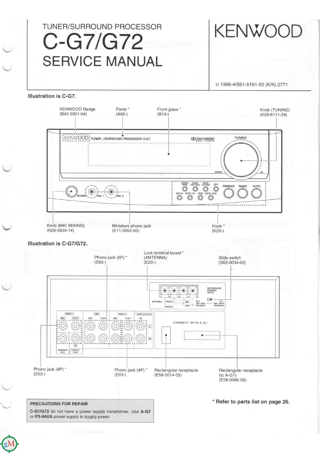
Illustration is 0-67.
KENWOOD Badge Panel ' From glass Knob (TUNING)
(543-0301-04) (A60-) (310-) (K29-61 11-24)
{giliilv- NEFI ISURRDLIND PROCESS}? 867
V
Knob (MIC MIXING) Minialure phone jack
V (K29-5839-14) (E1170262-05)
Illustration is C-GT/G72.
Lock terminal board '
Phone jack (6P) ' (ANTENNA) Slide switch
(E63-) (E20-) (862-0034-05)
~ flaw WWWW 5%
I mm mil! JL 21:, E m 12;!
r m W; ml
.
lmi fi
[NE [W
EDNNECY WIYM A-GY
E
l
l
l
Pth0 jack (4P) ' Phone jack (4P) Rectangular receptacle Rectangular receptacle
(E63?) (E63-) (E55-OOI4-05) (to A»G7)
(E58-0006-05)
, .
PRECAUTIONS FOR REPAIR Refer to parts lrst on page 26.

667/672 do not have a power supply transformer. Use A-G7
or PS-MUA power supply to supply power.

Page 2

C-G7/G72

EXTERNAL VIEW / REMOTE CONTROL

Illustration iS C-G72.

KENWOOD Badge Panel Front glass Knob (TUNING)

(343-030104) (A60-) (810-) (K294511124)
............. /
_|S!E_NWQQD' TUNER /5URFIUUND PROCESSOR (1672 III-

arr GE KEvouN /EAND#/AUI1:I
© ©
5cm

Ix
Knob (MIC MIXING) Miniature phone jack Knob '
(K29-5839-1 4) (E1 1026205) (K29-)

* Refer to parts list on page 26.

Remote control

v---~-y

Turm upmuan knya

BAND key. mum keys SLEEP kay
- fr 1
co pllyor opcnlinn k-y: pLTWEn k-y
T1ME .Press In swucn me nme display
"m" an I b .r k n i
Em MODE :Press In salm me am Iecoldlng W "" °"" "
mmav «ind»k=ys.~>l keys. bill key,
P.MODE Press for program playback. ' Y
I I
m m m d m mm ° ' DISC SKIP :Pvess m choose adusc.
proglarn
oustx :Pmss To display me ovogrammed
conlanu WI Old.
SFACE :Pmssmlelvanorrreoomedsoaces L
afalaw saconds bommnme pm-
grammeduacluv
mum :Fvess m sun ranaam playback. Numuic km (m, .m)

FEPEAT :Press m slarl recanted playback Funcuon as me numenc keys 0! me CD player
when The CD mom Is seleaed.
Function as the numeric keys :1 me lune! when

me TUNER Input :5 smacked

run-r worniun by!
W key. ADJUST key.
95. key. ENTER key

-%
TAPE opomlon luv:

These keys perform me samu npeminns as The
corresponding kays on [he cassene deck.
Howmmpamlonsreqymnq slmulvaneousmesy
mg ona key: am nol 9mm.

-

Sunound mm by: MUTE luv
DOLBY SURROUND key. on: kay Press (0 mule me sound (emporaniy.
omav :1 STEnEo kay, DELAY YIME keys. .
TEST TONE kay. CENTER LEVEL kavs, KEWOD VOLUME comm. km
REAR LEVEL key: " 2;" Press momma voiume
INPUT hy

Pres: [0 men [he component m be played.

Mndal - RC-GS
-__ Infrared ray system 3

Page 4

C-G7/G72

CIRCUIT DESCRIPTION

For Pre Tuner ii-com CXP82440A-XXXX. lnitial status and Back-Up, refer to the Service Manual of C-F5

1. Test mode

1-1. Initial setting

- When AC power cord is plugged while pressing the
AUTO/MANUAL key. equipment is initialized,

1-2. Test mode with the main unit keys

(1) Setting procedure
While pressing the BAND key. plug the AC power cord to
the power outlet.

(2) Cancellation
Unplug the AC power cord. The initial setting will take
effect and the test mode will be canceled.

(3) Description

1. Auto POWER ON

- When AC power cord is plugged while pressing the
BAND key, the POWER will turn ON and all function will
be at the initial setting. (Input selector=TUNEFt)

2. ALL LED 0N mode

0 When the AC power cord is plugged while pressing the
BAND key. all the LEDs will turn ON.

- When some main unit key is pressed. ALL LED ON mode
will be canceled all function will return the LEDs to nor-
mal.

3. Others

- The operation of main unit keys and remote controller

2. Microprocessor : CXP82440A-116 0 (c-G7)

: CXP82440A-131 O (C-G72)

2-1. Block diagram

keys during the test mode, refer to the table.

- The MUTE function does not work during the test mode.
(When POWER ON, MUTE is eflective.)

- Test mode is not canceled when the input selector is
moved TUNER to another source.

l m...
Key Selector ExcepllUiTUNER
Salaam TUNER - 7

KEY coN oEE kEV coN 0N

REAR LEin
Min -cemer -Mnx

Normal operation

r m r
r Amoco 0 mal operauurr (KEV CON UP)
CENTER LEVEL
Normal uperatmn
2 5mm, N Min -Canlar 4M!
l 5' mm" . (KEV CON. DOWN)
a KEV con DM'OFF mun KEV coN ON KEV cow. orr
Normal aperairon
. PRE. N , N
s5 CE P CALL DOWN nrmal operation [HIT MASTER CNOFF)
5 Drum r-no LOG Normalopelalion
a DOLBV a srzneo Normal uperaiiurr
7 or: Mormaluperatlon
rFREQUENCV ~TAPE MD 1
9 DEMO Lon « vioeoz LvioEol 4
9 TUNING Uproowu Normai operavmn Inhibit
r0 DlGlTAL ECHO Normal operation
u PRESET so PCALL up i Normal operation

12 l DlSPLAY ALL LEDS 0N -- OFF

|C11 l
.
Circuit control :
V'DEO '0 A/D. MUTE. RESET. CE :
DATAl , DATAZ . _ Serial communication
1 l SDATA. SBUSY
(NJM2279D) \
Ir \
IO. 7 x _____________________
Selector lC
DATA. CLOCK CXP82440A-XXXX
srRer - PRE TUNER u-COM
r' JU7311AL. A
v JU7313AL) FL control
E 5.
ICE Key matrix
DOLBV ic
DATA,CLOCK. .-
ENABLE I09 IC2 IC202 ICZOt |C2l
M2785) DELAY ic PLL IC nos IC RDS KEY CON. IC
DATA,CLOCK. DATA.CLOCK. mmcmcx, DATA.CLOCK,
ENABLE CE. DO RESET.START DEMODULATOH RESET.START
(LV1010N) (LC7218) (LCBS43H-4D68) (SAA6579) (MGSMOSP)
\\ RETURN KR 0 (19)
\ KFIt 15) KR2117 KR316
SCAN \\ C-G72 C-G7 ( I I I
KS 0 (68) #/AUTO AUTO PRESENCE DEMO - - - i
KS 1 (69) b/BAND BAND OFF PRESET E0. DISP
KS 2 (70) KEY CON. CENTER MODE 3 STEREO ECHO SURROUND
5 DS 0 (71) Dswo (037) - ~ - Dsw2 (039) - - -

C?

2-3.

No.

'U'U>>.XIZ-I-I>hmflafnrnrnrn'n'rlm'flItnlfnltxxx1-r-r-JIIA1-IAIA,,v-mmn--