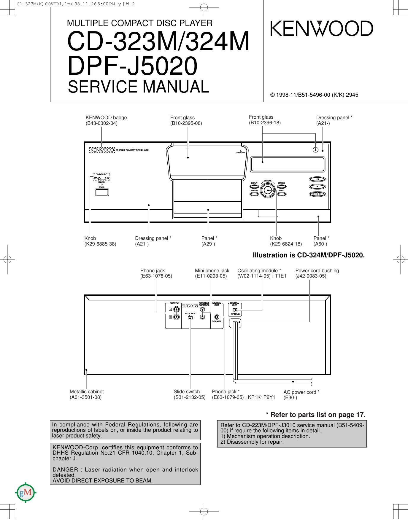
Kenwood CD 324 M Service Manual

This is the 17 pages manual for Kenwood CD 324 M Service Manual.
Read or download the pdf for free. If you want to contribute, please mail your pdfs to info@audioservicemanuals.com.

Page: 1 / 17
left right
Kenwood CD 324 M Service Manual

Extracted text from Kenwood CD 324 M Service Manual (Ocr-read)


Page 1

c97323M(K)co\/ER1,1p( 98.11.265:OOPM y [ w 2 /\

K

CD323M/324M KENWOOD
D PF-J5020

SERVICE MANUAL

© 1998-11/351-5496-00 (K/K) 2945

KENWOOD badge From glass Front glass Dressing panel
(343-0302-04) (810-2395-08) (B1 0-2396-18) (A2i -)

we... (L: =
:l

W /W\ m ..®
9. CC 9..
© ®

gl

_ I
Knob Dressing panel Panel Knob Panel
(K29-6885-38) (A21-) (A29-) (K29-6824-18) (A60-)
,\ Illustration is CD-324M/DPF-J5020. EA;
Phono jack Mini phone jack Oscillating module Power cord bushing
(E63-1078-05) (Ei 1-0293-05) (W02-1114-05) : T1 E1 (J42-0083-05)

mm ._ mm. m. m...
mmlxgammnm our M1
0

i:
ii
GT

0

:flI
Metallic cabinet Slide switch Phono lack AC power cord *
(A01-350i-08) (831-2132-05) (E63-1079-05) : KP1K1P2Y1 (E30-)

* Refer to parts list on page 17.

Refer to CD-223M/DPF-J3010 service manual (351-5409-
00) if require the following items in detail.

1) Mechanism operation description

2) Disassembly for repair.

In compliance with Federal Regulations, following are
reproductions of labels on. or inside the product relating to
laser product safety.

KENWOOD-Corp. certifies this equipment conforms to
DHHS Regulation No.21 CFR 1040.10, Chapter 1, Sub-
chapter J.

DANGER : Laser radiation when open and interlock
defeated.

AVOID DIRECT EXPOSURE TO BEAM.

Page 4

c97323M(K)COVER1,1p( 98.11.265:01PM y [ w

'7

CD-323M/324M/DPF-J5020

CIRCUIT DESCRIPTION

1-2 Microprocessor pin description (X32, ICB)

Pin No. Pin Name I/O Description

1 A16 0 No connection.
2 A17 0 No connection
2 NC - No connection.
3 S3-SW | Mechanism address detector switch.
4 SZ-SW | Mechanism address detector switch.
5 RD 0 SRAM read strobe.
6 WR O SRAM write strobe
7 81 -SW I Mechanism address detector switch.
8 ASTB(CE) O No connection.
9 VDD - Power supply (+5V).
10 +5VPUL 0 Disc sensor PWM output.
11 RTRN O No connection.
12 RWR O No connection.
13 RWRR O No connection.

14-21 L-DO-D7 O No connection.
22 TEST - GND.
23 DISC»SW | Disc sensor.
24 ROTARY-CW O Mechanism rotary motor (+). H 2 COW
25 ROTARY-COW O Mechanism rotary motor (-). H : CW
26 LOADM+1 0 Loading motor (+) for main pickup.
27 LOADM-1 0 Loading motor (-) for main pickup.
28 LOAD-SW1 | Loading switch for main pickup.
29 UNLOAD-SW1 | Unloading switch for main pickup.
30 CS 0 SRAM CS.
31 MON 0 Control port of poor focus works.
32 SCLK O Sens serial data read clock.
33 SENS | SENS signal input.
34 CLOCK O Serial data clock.
35 XLAT O CXD2587Q latch.
36 DATA O Serial data output.
37 VDD - Power supply (+5V).

38, 39 X1, 2 - Main system clock (12.5MHz).
40 V88 - GND.
41 XT2 - No connection.
42 XT1 | GND.
43 RESET | System reset signal input.
44 SCOR | Sub code synchro detection.
45 MUTEG O Muting control output. H : MUTE ON.
46 STBZ O No connection.
47 IC RESET 0 IC reset.
48 WE 0 Analog mute. L : MUTE ON.
49 SDATA I/O Serial data signal I/O.
50 SBUSY I/O Serial busy signal |/O.
51 AVDD - Power supply(+5V).
52 AVREF - A/D reference power supply.
53 NBC | Model selector.
54 8/16 | 8/16 bit selector. H216bit.
55 JOG2 | Encoder signal A input.