Kenwood Basic M 1 Service Manual

This is the 14 pages manual for Kenwood Basic M 1 Service Manual.
Read or download the pdf for free. If you want to contribute, please mail your pdfs to info@audioservicemanuals.com.

Page: 1 / 14
left right
Kenwood Basic M 1 Service Manual

Extracted text from Kenwood Basic M 1 Service Manual (Ocr-read)


Page 1

)IfiVIC: filAI'IUAL

® KENWOOD BAS'C M

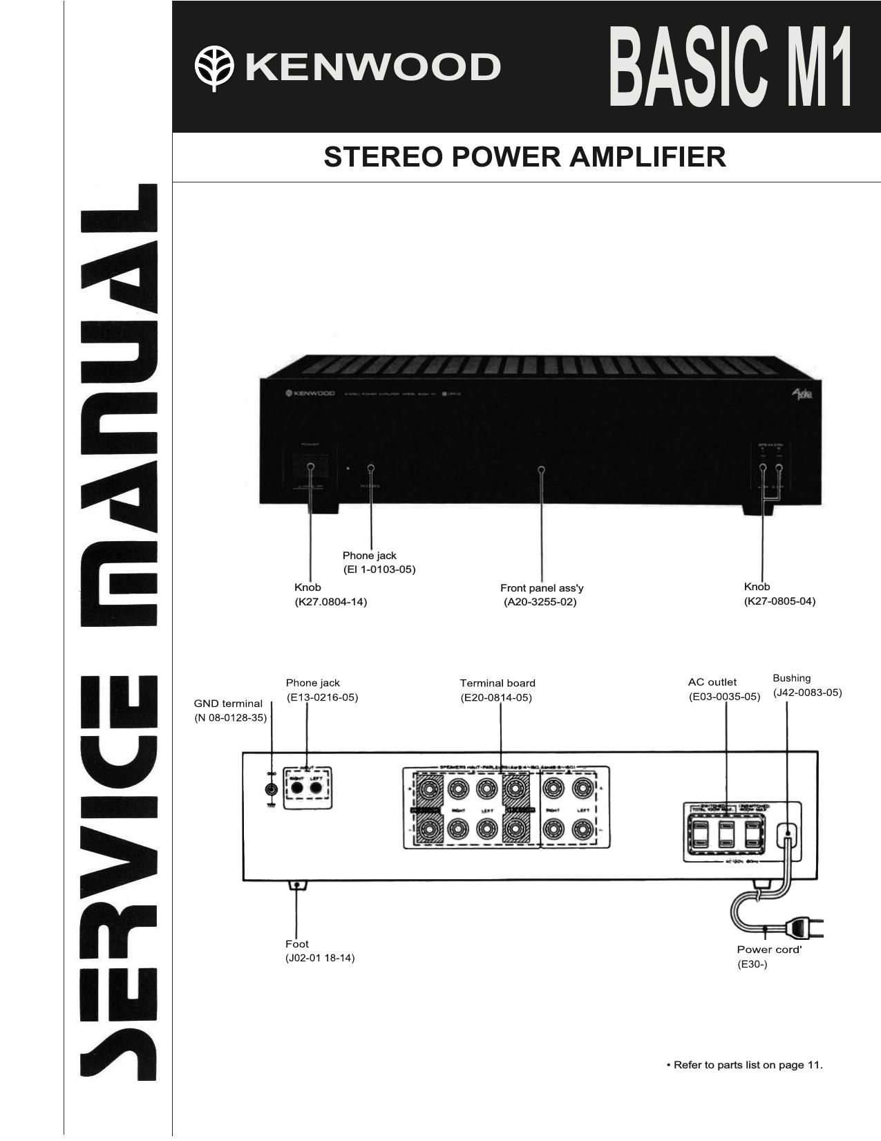
STEREO POWER AMPLIFIER

Phone jack
(El 1-0103-05)
Knob Front panel ass'y Knob
(K27.0804-14) (A20-3255-02) (K27-0805-04)
PhOne jack Termma board AC outlet BUShing
' - , 7 , , (J42-0083-05)
GND terminal (E13 0215 05) (E20 0814 05) (E03 0035 05)
(N 08-012835)

ECU

.1..-

Power cord'
0230-)

Foot
(J02-01 18-14)

- Refer to parts list on page 11.

Page 2

ADJUSTMENT! REGLAGES

INPUT OUTPUT AMPLIFIER ALIGMENT
"° "E" ssnmos ssrrmos ssnmc points '6" F°R no.
Connect a DC After 5 minutes. adjust
1 IDLE voltmeter VOLUME : 0 was (L) VR3 ivm) for e~20mv
cunnsur - across R113 POWER : ON vna (Ft) reading oi the DC is)
(R114) voltmeter.
Power Amplifier Chuck

After completing power amplifier repairs, be sure to con-

firm that waveforms are present as indicated below. Power

amplifier operation is not normal if these waveforms cannot
be observed.

[ Test Conditions ]

1. Apply a 50H: sine wave to the AUX terminal.

2. Connect an 8 ohm dummy load to the speaker terminals.

3. Connect the (+) lead of the oscilloscope to pin 14 of
X133520~1L and connect the (-) lead to pin 11 (L) or
pin 12 (R) of X07-1940-11.

4. Set the volume control of the BASIC M1 to 0. the selec-
tor to AUX. and the REC OUT control to OFF, then
turn on the power.

5. When the volume control of the BASIC M1 is turned up
slowly, the waveform shown in Figure A should appear
suddenly at a certain point. This is evidence that the
high output circuit has begun operating. Stop turning
the volume control at the point where this waveform
appears.

6. Momentarily turn off the power to the BASIC M1.

7. Connect the (+1 lead of the oscilloscope to pin 15 of
X13-3520-11, and connect the (-) lead to pin 13 (L)
or pin 14 (R) of X07-1940-11.

8. Turn the power to the BASIC M1 back on.

9. The waveform shown in Figure B should appear. It is
not possible to observe both waveform A and B at the
same time. Be sure to observe them individually, and be
sure that no other test equipment is connected to the
amplifier at the same time as the oscilloscope.

Note:

A self-restoring thermal switch is built into the power trans-
former. This switch is activated to cut output of the trans
former when its temperature rises beyond 150° C. The
amount of time required for recovery is approximately 5
minutes.

REGLAGE DE
LA SORTIE

HEGLAGE

N "EM L'ENTREE

REGLAGE DE
'AMPLI FICATEUR L'AIGNEMENT

poms 9 ALIGNER POUR FIG.

Connector un
voltmetre CC
sur RllBiRiM)

1' COURANT DE
POLAR ISAT|ON

VOLUME : 0

Aprés 5 minutes. régler
VR3 (VH4) de lawn s
ce que la voltmétre de 3
(LC. indique 8~2Drnv.

VR3 (G)
VRA (D)

verification do l'amplificamur do puisunee

Apres avoir effectué les reparations de l'amplificateur de

puissanoe. s'assurer que les ondes existent dans les condi~

tions indiquées ci-dessous. Le fonctionnement de I'ampli~
ficateur est anormal si oes ondes ne peuvent étre observées.

[ Conditions d'emi I

1. Appliquer une onde sinusoi'dale de 50H2 6 la borne
AUX.

2. Appliquer une charge "dummy" de 8 ohms aux homes
des enoeintes.

3. Relier Ie til d'alimentation (+) de I'oscilloscope a la
broche l4 du X133520<1 1. et relier le ill d'alimentation
(-) a la broche 11 (L) co 5 la broche 12 (R) du X07-
1940-11.

4. Placer le réglage de volume du BASIC M1 sur 0", Ie
sélecteur sur AUX, et la commande de sortie denregistre-
ment REC OUt" sur "OFF" avant de mettre sous
tension I'appareil.

5. Lorsque Ie réglage de volume du BASIC M1 est Iente.
ment torné dans le sens d'une augementation cle volume,
l'onde indiquée sur la figure A doit sudainement apparel-
ture 5 un moment donné. Cette onde est la preuve que Ie

haut circuit de sortie a commencé a fonctionner. Arréter
le mouvement de la commande de réglage de volume au
moment oi; I'onde decrite apparait.

6. Mettre momentanément hors tension le BASIC M1.

7. Relier Ie til d'alimentation (H de loscilloscope a la
broche 15 du X133520-1l.et relier le fil d'alimentation
1-) a la broche 13 (L) ou a la broche 14 (R) du X07-
1940-11.

8. Mettre de nouveau sous tension Ie BASIC M 1.

9. L'onde indiquée sur la figure B doit apparaitre. II est
impossible dobserver les deux types d'ondes en meme
temps. Veiller a les observer séparément et s'assurer
qu'aucun autre materiel d'essai est raccordé a l'ampli-
ficateur en meme temps que I'oscilloscope.

Remuque :

Un commutateur thermique é auto-déclenchement est
incorporé au transformateur de puissance. Ce commutateur
est active pour couper I'alimentation du transformateur
Iorsque sa temperature s'éléve au dessus de 150' C. Cinq
minutes sont environ necessaires pour que Ie transformateur
soit de nouveau mis sous tension.