Kenwood AT 300 Service Manual

This is the 23 pages manual for Kenwood AT 300 Service Manual.
Read or download the pdf for free. If you want to contribute, please mail your pdfs to info@audioservicemanuals.com.

Page: 1 / 23
left right
Kenwood AT 300 Service Manual

Extracted text from Kenwood AT 300 Service Manual (Ocr-read)


Page 1

AUTOMATIC ANTENNA TUNER

AT-300

SERVICE MANUAL

KENWOOD

© 1991~1 PRINTED IN JAPAN

851-810000 (O) 996

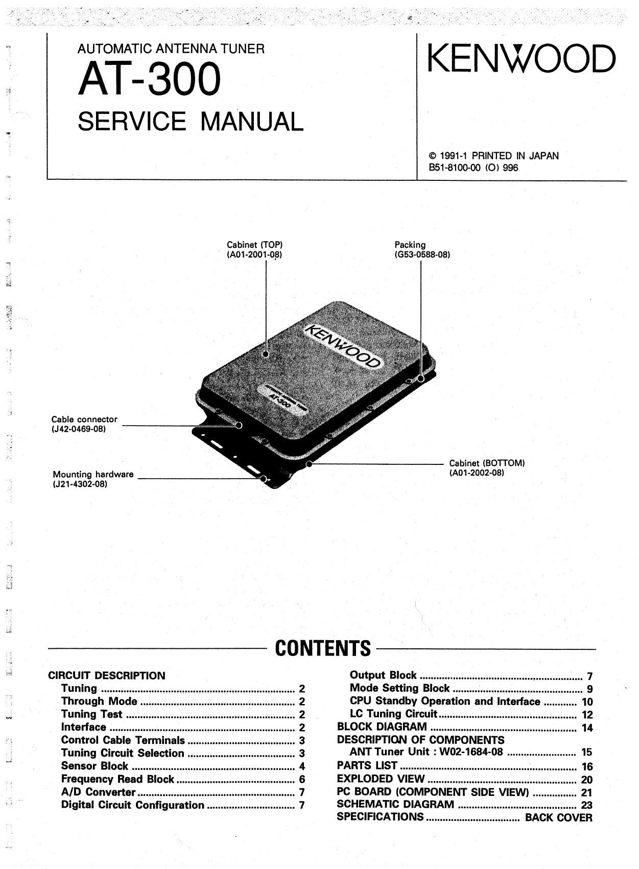
Cabinet (TOP)
le1-2oo1-og)

Cable connector
(J 42-0469-08)

Mounting hardware
(J21 4302-08)

CIRCUIT DESCRIPTION


Packing
(G53-0588-08)

Cabinet (BOTTOM)
(AD1-2002-08)

CONTENTS

Output Block ........... l ......................................


Tuning ................. Mode Setting Block ............................... .. 9
Through Mode CPU Standby Operation and Interface . 10
Tuning Test . LC Tuning Circuit 12
Interface BLOCK DIAGRAM .. 14

Control Cable Terminals .
Tuning Circuit Selection .


DESCRIPTION OF COMPONENTS
ANT Tuner Unit :W02-1684-08

NNQthMNNN

.. 15

Sensor Block PARTS LIST ....... 16
Frequency Read oc . EXPLODED VIEW 20
AID Converter ............... PC BOARD (COMPONENT SIDE VIEW) .. 21
Digital Circuit Configuration . SCHEMATIC DIAGRAM 23

SPECIFICATIONS

RACK coI/ER

Page 2

W.

i: KENWOOD M

Am I i cati 0 n N Ote Amateur Radio Division

Subject: AT-3OO Mobile Tuning Notes. Date: November 30, 1993

The new Automatic Antenna Tuner is capable of tuning a relatively large SWR mismatch when it is used in
conjunction with any modern Kenwood Transceiver. The tuner was designed specifically for use, in fixed station

applications. but some users have indicated a desire to use the tuner in mobile applications. This can cause a
number of problems to occur. One such problem might be that the engine of the vehicle would stop when the AT-
300 is being used. This is the reason the tuner is not recommended for use in mobile applications! Users who
desire to experiment with this type of installation can try the following changes:

Procedure:

1. Remove the cover of the tuner and locate resistors R56 and R57. These are located near lC4.
2. Remove the two resistors.

3. Next locate terminals J5 and J6.

4 Solder a short iumper wire between these two jumpers.

w Note: These changes will improve the matching capabilities of the tuner when used in experimental mobile applications. It Is
important to note that for product liability reasons Kenwood Americas Corporation, Kenwood Communications Corporation, and
Kenwood Service Corporation do not recommend that the user Install the timer In mobile applications under any circumstance.

; Time required for this modification is 30 minutes or less.
5.. ©113093 by CLM for Kenwood Service Corporation Page 1 of 1

Page 5

CIRCUIT DESCRIPTION

mono BK
@TT BL

@euo 1

0 NC
. 63/1 0 TS
Rd O+DC
- AT-300 TS-850

Pin name Description Pin name Description

+13.6V 13.6V DC input . GND Ground

GND Ground Ti Control signal input/output

TS Control signal input/output GND Ground

TT Control signal input/output NC Unused
TS Control signal input/output
+DC +13.8V

Fig. 2 Control cable connection

Sensor Block

An attenuator consisting of R1 through R7 is in-
serted into the sensor to stabilize impedance and re-
duce unwanted waves during tuning. High power sig-
nals are input from the remote controller to the J1 ter-
minal and passed through this attenuator.

The high power signal is tapped off from the main
signal and passed through R11 to the frequency read
block.

The forward wave and reflected wave signals of the
HF signal are detected by a coupler consisting of L12,
L13, R9, and R10 ; converted into a control voltage
using 01 and D2 ; then sent to the analog-to digital
converter.

The converted digital signal is used as an input sig-
nal for the input power check and reflection coefficient
operation.

The forward and reflected waves are sent through
buffers 01 and O2 to a DBM consisting of L16, L17,
and 047 and sent to comparator IC15 (1/2) as imped-
ance signal lZl. Impedance signal IZl is compared with
a 50-ohm impedance.

Voltage and current signals are sent to a DBM con-
sisting of L14, L15. and D46 ; compared with each
other, then extracted as a phase signal.

input power level range : 8 ~ 15W.

- Overpower .

When power exceeding approximately 20W is de-
tected during the power check, a looms counter is set.
When a tuning start (TS) is canceled after 100ms or
within 100ms, the through mode is entered.

1 : Power check

2 : TS check

3 :Retumed to 1 if within looms

If the power is proper in step 1. stop the above
operation and proceed to the next operation.