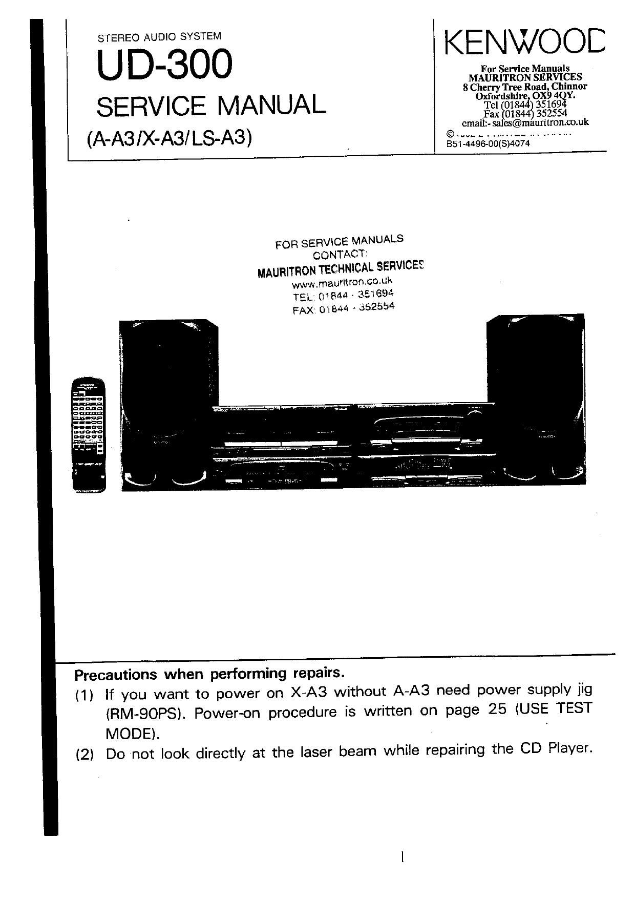
Kenwood AA 3 Service Manual

This is the 134 pages manual for Kenwood AA 3 Service Manual.
Read or download the pdf for free. If you want to contribute, please mail your pdfs to info@audioservicemanuals.com.

Page: 1 / 134
left right
Kenwood AA 3 Service Manual

Extracted text from Kenwood AA 3 Service Manual (Ocr-read)


Page 1

KENWOOE
U For Service Manuals
MAURITRON SERVICES

8 Chem Trey Road Chinnor
SERVICE MANUAL °¥2f8lé23°3§?593
Fax $018443 352554
cmallz- salcs@mauntron.co.uk

(AAS IX'ASI LSA3) . alabaoagslaaa " "

FOR SERVlCE MANUALS
CONTACT:
MAURITHON TECHNICAL SERVICES
www.mauritron.co.uk
TEL; 01844 - 351893

FAX: 01844 - 352554

Precautions when performing repairs.

(1) If you want to power on X4A3 without A-A3 need power supply jig
lRM-QOPS). Power-on procedure is written on page 25 (USE TEST
MODE).

(2) Do not look directly at the laser beam while repairing the CD Player.

Page 2

U D-3OO

CONTENTS

AMPLIFIER (A-A3)
DECK, CO, TUNER(X-A3).
CONTROL AND INDICATOR ......................................... 5
REMOTE CONTROL UNIT
SYSTEM CONNECTIONS.
DISASSEMaLY FOR REPAIR
BLOCK DIAGRAM
AMP SECTIONI.I...I.........I...I.u.
TUNER SECTION.
CD SECTION.....
DECK SECTION17
CIRCUIT DESCRIPTION .......
MECHANISM DESCRIPTION.
CD PLAYER ...................
CASSETTE DECK ........................................................ 50
ADJUSTMENT .................................................................... 58

ACCESSORIES

0 AM Iooo antenna .. I . FM Indoor amenna I

USO-1317405) (T900175-05)

- Remote zonIrOI un-I I - Bananas (Ros/AN 2

ha
an
II

(X944 0qu 1)
BATTERY COVER
(Ans-0126413)

L

can
an:
aaan
can
Dunn

I. 8 $2 INSTRUCTION MANUAL

EGO-075100 (ENGLISH) EGO-075500 (ITA) E
EGO-075200 (FIRE) RE
EGO-0753430 (GER) E
55041754430 (JAP) E

AMPLIFIER (A-AS)
WIRING DIAGRAM ..................................................... 59
PC BOARDI....,W......
SCHEMATIC DIAGRAM

CASSETTE DECK (X-A3)
WIRING DIAGRAM 51
PC BOARD ................ - ............................................... a 2
SCHEMATIC DIAGRAM

EXPLODED VIEW.
CD MECHANISM
CASSETTE MECHANlSM....,......I....,...............

-70
3

SPEAKER .........................................................


SPEC!FICATIONSI.............,_...I..I..m._...,_.............

. Amemu mum. I
(75 [1/300 III
(Encem In: some areas!

0 AC plug adapIOr I
(Except (or some areas)

\

(503-01 ISOSIM

(TBO-OIBS-OSITE

Arum: haldcr

(J 1 max 54m

BSD-0756430 (CHI) M
BEG-075700 (SPA) M,E
BED-0756430 (AHA) M

Page 7

CD operation keys
PMODE: Swntches the play modes.

CLEAFI : Clears a selected track Itomthe
program.

CHECK : Checks the tracks selected In the
program.

EDIT : Swutches the editing modes.

SPACE : Dunno recording. creates a non-
recorded space of 4 seconds
between tracks.

REPEAT : Plays trackls) reoeatedlv.

TIME . Swutches the time display.

Numeric keys
How to enter numbers:

To enter 20 -- +M10 %
3

UD-3OO

REMOTE CONTROLLER

POWER key

( r AUTO :
P.CALL I


KENWOOD

aeru'a-re comm. um
HC-Aa

EEfi'flaa
(55315133

To enter 23 ..
Graphic equalizer operation keys

EFFECT : Tums the graphic equalizer
effects ON/OFF.
MCALL : Each press recalls a pattern

from memory.


Tuner operation keys

ADJUST: Adjusts the time of day,

TUNING: Tunes a statlon.

Swttches the tuning modes.

Recalls the preset stations.

FROG. ' Modifies or checks the
programmed contents.

EXE. Executes the program.

BAND : chtches the broadcast oanos.

SLEEP . Sets the sleep timer.

Deck A operation keys

Deck 3 operation keys

PRESENCE : Switches the presence
modes,

OFF : Tums the presence mode
OFF.

N B CIRCUIT: Reproduce: more natural
bass sound.

MUTE key

Reduces the volume temporarily. The Indica-
tor on the VOLUME CONTROL knob blinks
whlle muttng is active.

MASTER VOLUME control key:

Input select key:

Adjusts the volume. While these keys are
operated, the VOLUME CONTROL knob on
the main umt rotates and the indicator on It

blinks at high speed.

FOR SERVICE MANUALS

CONTACT:

MAURITRON TECHNICAL SERVICES

www.mauritron.co.uk
TEL: 01844 » 351694
FAX: 01844 < 352554

Page 11

DISASSEMBLY FOR REPAIR

©Remaving the CD mechanism.
11) Remove 4 screws 0 .
12) Remove F03. Q .

@Removing the tuner PCB.
13) Remove 2 screws Q.

FOR SERVICE MANUALS
CONTACT:
MAURITRON TECHNICAL SERVICES
www.maudtroncauk
TEL: 01844 ~ 351$94
FAX; 01844 - 352554

14) Remove me tuner PCB from connector. Q .

u
E] W
a F 5L.
a? -#
|
3 EM
5 El
9
REAR PANEL
g 69 X32-2220-IO
f (5/2)
2.1 V I1 r
glgfl

11

Page 41

U U-BUU

CIRCUIT DESCRIPTION

Digital Signal Processor : CXDZSOOAQ (ICE)

Outline

The CXDZSOOAQ is a digital signal processing LSl for a

compact disc player, which has the following func-

tions.

0 A wide frame jitter margin realized by 32KRAM (:28
frames)

. Bit clocks for strobing EFM signal are generated by
the digital PLL, and the capture range is :lsokHz
minumum

- Demodulation of EFM data

- Protection and reinforcement of EFlvl frame sync
Signal

- Strong error correction by refined super strategy.
C'l :Douoie correction, C2 :Quadruple correction

- Double-speed replay and variable pitch replay

- Reduction of noise generation at track jumps

0 Auto zero cross muting

- Demodulation of subcode and detection of errors in
sub-code 0 data

Block diagram

rsll
XIAI
XIAO
XYSL
VCKI
vrco

- Digital spindle servo (Having over-sampling filter)
16-bit traverse counter

CPU interface by serial bus

A built-in servo auto sequencer

0 Output for digital audio interface

- Built-in digital level meter and peak meter

- Applicable to bilingual system

a 0

Features

. One chip of this LSI can process all the digital sig-
nals used for replay

- Integration level can be heightened because of the
built-in RAM

Structure
Silicon gate CMOS

AVao
Cm cuu AV
Cisu mum m u \m
P00 Vu-
vcor mum m m E V
vcoo ""4 mum-m 3 Va:
uuur m. 2 Hum mum
Pca i: mum: mm:
FILI FSSL
FILO
SIM
CLIV n: mu owl-is
as M
m. mun-i
ASVU HIUII
wrcx mum MUIE
scan
Excx mm. m- um."
5950 ".521.
EHPN mum wt DOUI
socx mg... MDZ
Snso .VIKIIICI
HON 3 in" "Hui-f DATA
w 2 ml rum-u CLOK
no? i m XLAI
M05 Inunu

h-Inl
nnmuz

"I" wit-n
nun-u m
HIIH

Illlll

rest
at:

XRSI
LOCK i

APIR
APIL
LRCK
IDCK

DATO
CLKO
XLTG

SEIu
SENS
MIMI
CNIM
four I

41

Page 62

U U-JUU

CAUTION

ADJUSTMENT

Pickup (KSS-24OA) is adiustment free in repairing.
please don't disassemble and adjust Ii.

Tracking balance

VRZ


KSS , 240A

Focus bias
VRJ

VRI

RF levll LD POWER

INPUT OUTPUT PLAYER ALIGNMENT
to ITEM SETTING SETTING SETTING POINT \LICN F0? FIG.
Short~circuit 91:15 On the newer {mm
TEST and enter the 008 to Otis-l. when
Iest node, , the diffraction
Apva the sensor [grating is correctly
section of the Dvlical Press me play key . Ham mn the RF
1 L.~.S|2il PCIER - voer meter on the - level or I SVD'D or (a)
Pickup lens to checKthal more and the TE
X the LD emits light (servo oven) level
or |,SVp-n or more.
Thenoonhrm that V
the pickup is
the display is "05 acceptable
Test disc Connect a LP? to CM
Typel pin 24, to which Press the PLAY key,
2 FOCLS CAIN rIPPIy signal of connect an oscilloscope Confirm thal the FOCUS GAIN Two VTVI: Should read (b)
1.0tz 0 Wm: to or [no AC VOIlmelErS disvlay is 05". VRZ the 53:: value.
CM PHI 2 and it
Test disc Connect 2 LP? to CR3
IYDE I viii 5-5. to which Press the PLAY key,
3 TRACMXG GAIN Avuly signal or connect an osciltakopc Confirm Hut the TRACKINE GAIN Tim VTVls should read It)
1.0kllz, 0 [Iran to or two AC vaitmeters. display is '05'. YR] the should value.
CNII pin 5 and 6

(NOFE) True 4 «is: V

LPI': around 47kohns>HOeF or so.
Adiustmciit pres-cures are in TES. MODE,

(3) Laser Power

Pickup

KHAVE TO TAKE AWAY THE SUB-CHASSISI
)From CD MECHA ASS'Y.

AND PCB(

62

0.08 - OJSmW

Om Ical {>0on mete:

SONV YEDS~IB TEST DISC or lQMIVIIEnlt

(b) Focus Gain and Tracking Gain

Focus gain :

Tracking gain :

Page 63

REGLAGE

U LJ'OUU

REGLAGE DE REGLAGE DE LA REGLAGE DU POINTS DE
N ' ITEM
L'ENTREE sonne LECTEUR L'ALIGNEMENT AL'GNER POUR FG'
Coun-circuiter ies Sur l'alimentation
broches TEST 9! de 0,08 a OISmV
passer dans la Iorsque la grille d6
mode dessai. difiraction est
la
ALIMENTATION Appiiquer la section de ADDUYEV 5W ficrr§ectemant
1 LASER - cameur du sompteur touche de lecture _ augnee avec le (.2)
x , . . , pour vérflier qua \e niveau RF de
d ahmemamn vphqua ,
. . LD amel de la 1.5Vcc ou ptus a!
sur lopthue d3 edure. ..
kumlere Is mveau TE [servo
Ensuiteyérifier que ouvem de 15/05
laffichaga est cu plus, is lecture
"05" , est acceptable.
Bisque dessai
Type 4 Cunrecter un LPF aux Appuyer sur la VTVM a ' {
en
Appliquar un signal we: CNS 2 at 3 touch? 19 lecure- GAIN DE FOCUS 0:51? w la (":18
n , .
2 6 DE FOCU" de 1,0kHz.0.1Vrms We? Nectar Venfie'que VR2 We (D
aux brochss CN3 dun oscxuosfepe :: Iamchage 95 '
Zeta euxvomers . 05.
Bisque d'essai
Type 4 Conneder un LPF A
A l uer u aux crashes CN3 5 e1 ppuyar sur 3 _ _ .
GNN DALGNE- p, " 6 auxquelles cm touche d9 lecture. GAIN DALIGN:- Deux VTVM don/em
3 MENT 5|gnal d9 n d r m os~illosco Venfiar que l'af- MENT rndiquer Ia merne (b)
1'0- 0-1 Vrms sued voxmtrespe fichage est "05 . VR1 valeur.
aux broches CNS 0 aux e
5 e! 5. Ac-

(NOTE) Bisque type 4:DISOUE DESSAI SONY YEDS-1B ou équwalent.
LPF:environ 47 kohmsBSO pF la peu prés
Les proc'edures de réglage se fonxdans Ie MODE DESSAI.

FOR SERVICE MANUALS

CONTACT:

MAURITRON TECHNICAL SERVICES
www.mauritron.co.uk
TEL: 01844 - 351694
FAX: 01844 - 352554