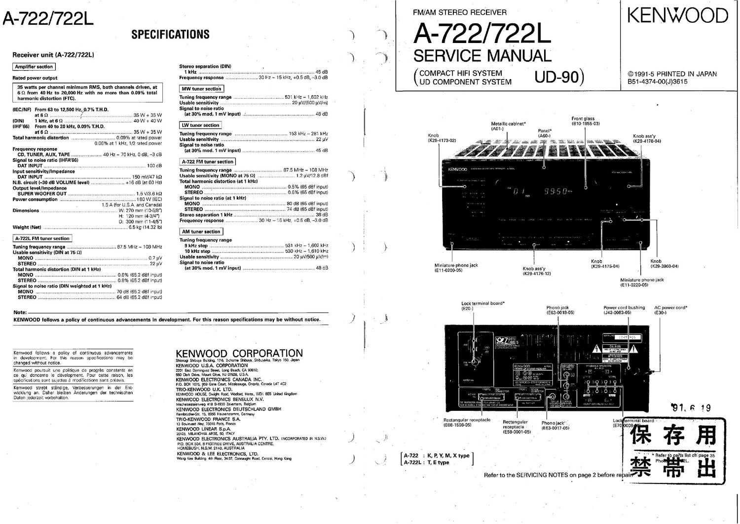
Kenwood A 722 Service Manual

This is the 21 pages manual for Kenwood A 722 Service Manual.
Read or download the pdf for free. If you want to contribute, please mail your pdfs to info@audioservicemanuals.com.

Page: 1 / 21
left right
Kenwood A 722 Service Manual

Extracted text from Kenwood A 722 Service Manual (Ocr-read)


Page 2

A-722/722L

CONTENTS

SERVICING NOTES .................................................................. 2
PACKING .................................
CONTROLS AND INDICATORS
DISASSEMBLY FOR REPAIR
BLOCK DIAGRAM ................
CIRCUIT DESCRIPTION ..............................


3
..4
..5

6

7

SERVICING NOTES

(D This unit does not contain a selector IC. Since each speaker
relay of this unit is operated according to the data that is
serially transmitted from the graphic equalizer (GE-722), the
receiver cannot output sound alone. To output a signal to
each speaker terminal, follow the following procedures.

Procedure 1)

Direct the tuner output to the main amplifier input Connect the
test pin on the right (lower right of the tuner board) of the main
amplifier board (X09, A/8). (Fig. I)

Pins 12 and 10 (Left channel)

Pins 13 and 11 (Right channel)

Presence amplifier Pins 12 and Rl45 lead (Presence left
channel)

Pins 13 and R146 lead (Presence right
channel)

Front amplifier

ADJUSTMENT ................................................ 16

PC BOARD (Component side view) 19
SCHEMATIC DIAGRAM 23
EXPLODED VIEW 31

PARTS LIST
SPECIFICATIONS

Procedure 2)

Enter the test mode. (Hold down the CHARACTER key, and

insert the AC plug into the outlet.)

1) Press the DAT key. (Only the front speaker outputs sound.)

2) Press the VIDEO key. (The DSP surround four-channel mode
is entered, and the front, rear, and center speakers output
sound)

3) Press the DBS/LD key. (The DSP front four-channel mode is
entered, and the front and presence speakers outputs
sound)

3

(If)

A-722/722L
PACKING

The A-722 is supplied with all the accessories, except the

remote controller (Am-053505) for the GE-722.

Protection bag (H25~0232-04)

Instruction manual* (560»)
Protection bag . .
(H25-0232»04)
t I
f

f j/ p ,

Polystyrene foamed fixture *

(H10-)
Polystyrene foamed
fixture (H10-)
\
Upper part
Polystyrene fi
surface
\ WM \x\\\\\\\
DP-722
E]
9 GE 722
a _
/ 3 :«t E
/ a x 72
E - 2
N a E
g 8
Item canon case* <
(HBO-I
Serial number of system is on box
for receiver
* Refer to parts list on page 35 Arrangement of components as
viewed from window in other box
The sleeve method is K, Y, M types, and E, X, T types are corru-
gated fiberboard boxes.
Accessories
. AM (MW LW) loop antenna _____ 1 I FM indoor antenna .................... 1 0 Batteries (ROG/AA) .................... 2
(TEN-017305): Japan made (T90-0176-05l: Japan made
(T90-Ol74-05): Singapore made (T900175'05I3 Singapore made
. Loop antenna stand o Antenna adaptor (75 0/300 9) .. 1 0 AC plug adaptor ........................ l
(J19.2815_04) (A-722L only) (T90-O136-05) (M type only) (E03-0115-05)
to ,
= I