Kenwood A 711 L Service Manual 2

This is the 40 pages manual for Kenwood A 711 L Service Manual 2.
Read or download the pdf for free. If you want to contribute, please mail your pdfs to info@audioservicemanuals.com.

Page: 1 / 40
left right
Kenwood A 711 L Service Manual 2

Extracted text from Kenwood A 711 L Service Manual 2 (Ocr-read)


Page 1

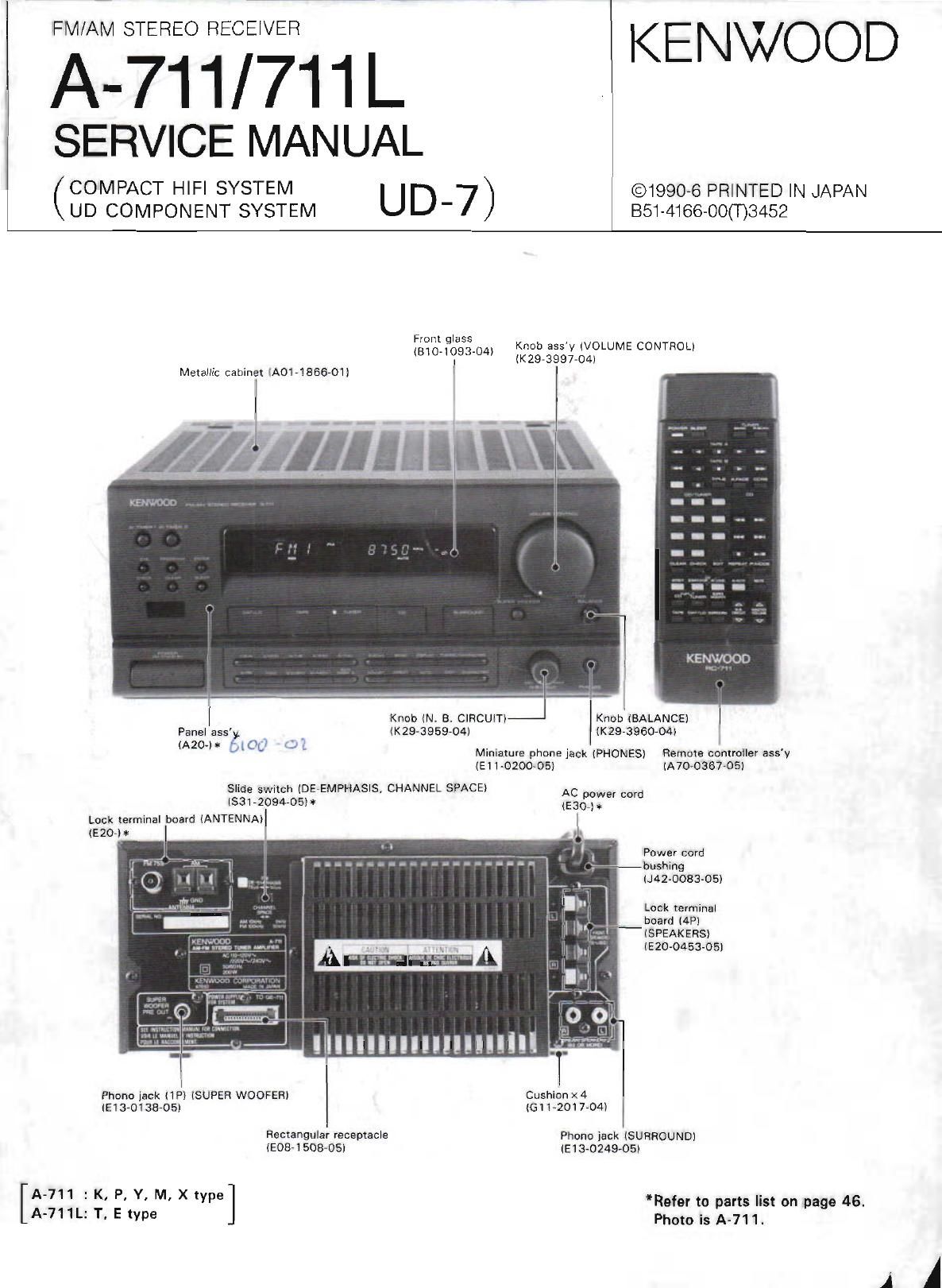
FIVl/AM STEREO RECEIVER KENWOOD
A-71 1/ 71 1 L

SERVICE MANUAL

(COMPACT HIFI SYSTEM U D 7 ) ©1990-6 PRINTED IN JAPAN
UD COMPONENT SYSTEM ' EST-4166700033452

From glass
, , Knob assy lVOLUME CONTROL)
310093 04) mas-3997434)

Metallic cabinet 1A0171866701l ll

l
M1111]! I" iffiK

mm


KENWQOD

| Knob (N. 5 cmcum-J KnoblBALANCE)
Panel ass'g (K297395904) les-ageo-om
, l
(A20 [0 U Mlniature phbne jack (PHONES) Remote controller ass'y
(El 10200-05) (Aromsros)
Slide swutch (DEVEMPHASIS, CHANNEL SPACE) AC
lsal-QOQLOSH was? mm

Lock terminal board (ANTENNA)
(EZO-H

Power cord
ibushing
4200830 5)

Lock terminal
board (4P)

(5 PEAKERS)

(E 20-0453705]

l
Phonn jack (lPl lSUPER WOOFER) Cushionx4

(930133435, lGll)2017-04l
Rectangular receptacle Phone jack (SURROUND)
[9337150805] (93024905)
[A-711 : K, P. Y, M. X type *Refer to parts list on page 46.
A-711L: T. E type Photo is A-711.

A A

Page 2

A-71I/711L

CONTENTS

NOTES REGARDING SERVICES OF THIS UNIT AND
FEATURES OI" SYSIEI .

PACKIIG ....................
SYSTEM CONNECTIONCt
COH'hOLS ,J.[i (XDI
OPERATION O": H .
DISASSEMBLY FOR REPAIR... .. .. .. ...
BLOCK DIAGFM.

.>\imml>com

CIRCUIT DESCRIPTION, .. .. . ll

.. 27

ATJLJSTI.IENT. .. .. ..

PC BOARD (Component Slde vewl 29
SCHEMATIC DIAGRAM 35
FXPLODED VIEW .. 44

46
. Back cover

mms LIST. .
SPECIFICATIONS.

NOTES REGARDING SERVICES OF THIS UNIT AND FEATURES OF SYSTEM


I BI'S"810"I"V nsm Y" "t it I c L. 7 1 *" .5
syst ur tho Oi r ll'fin

2 "(3 unit i I "ace vu flat is mounted VVIII
iiti'w'niv I,aS'IJP~I_SE." "OFICM . .
Ilir- graphic "(Ida 7w: .rET/l' ,S'1FIF£S\/,r"rr 11>»; ihrodgp

the graphic equalm Thererw, radio waves cannot be
nice «ed v. m this M elm ,.

\I\I:.Il'} you Hui-J 1' Hair v. '
nection mus: be rrtide by 19': (blowing mel".id.
[II T.
method

(Instead of tuner output, AG output can aiso be connected
to X09 Sidel

- with his iirr 1'iIII31 cone

[52. connctlic "99 Hip 1" I-g .Ir'm irnec Tr"

a) Facilitated connection method (It can be connected at
once after case is opened]
Connect lbw nitriiit : il TD" I NH and A IPchl in! " _, :0"
board [XUb, A'6I W (3 test DI ': ism-7:31;"!
ol "tam board (XDQI (8(5). (Output decreases
par'ly because of (I'IM relation Iiip. 'r-wpeoancel

b) Regular connection method (Refer to disassembling
method for repair)
Connect :nntpamv " I. ' an: .I Ln-wcti it (FZLIHIHI

/T/

i.
/ 'rpwmb )33YIP24GNDI

/r\/\

s \ t
., .
i
I V
\
b IX05IIA/6I

(in;

I JITP7IL chi
.. TPBIGNDI
iPQ(R ch]

boaro 1X05. A/6I which stands against the rear wall with
lead wire (for input) o( RT (Lch) and R2(Rch) of main board
(X09) (A/5) which is installed below the tuner board. With
this ct: _ ion, action of the surround circuit which cannot
be checked with procedures of a) for output can be checked.
< Fig 2> (Be sure 10 Connectthe GND of tuner board IX05.
NS) for activatlng the mic'oprocessor normally With (END
of chassis this time)

3. The small radiator cover (5 attached to this unit Use it to
check power transistors and so on by removing it. In addi-
tion, the main board can be checked by removing the bot~
tom board after detaching the case from the unit. (For further
detail, 'efer to the disassembly method (or repair)

4. As a new function. one pattern of graphic equalizer has be-
come able to be selected and stored into memon/ at each
INPUT SELECTOR The memory can be conducted by GE
microprocessor. The REC level set by CRLS at each INPUT
SELECTOR (excluding TAPE} can also be stored into
memory. The memory can be conducted by DECK
miiroprocessor.