Kenwood A 5 L Service Manual

This is the 52 pages manual for Kenwood A 5 L Service Manual.
Read or download the pdf for free. If you want to contribute, please mail your pdfs to info@audioservicemanuals.com.

Page: 1 / 52
left right
Kenwood A 5 L Service Manual

Extracted text from Kenwood A 5 L Service Manual (Ocr-read)


Page 1

FM/AM STEREO RECEIVER KENWOOD
A-A5/A5 L

SERVICE MANUAL
(83%?ISEOHIE'NiY§$§¥EM UD-EOO/SOOM)


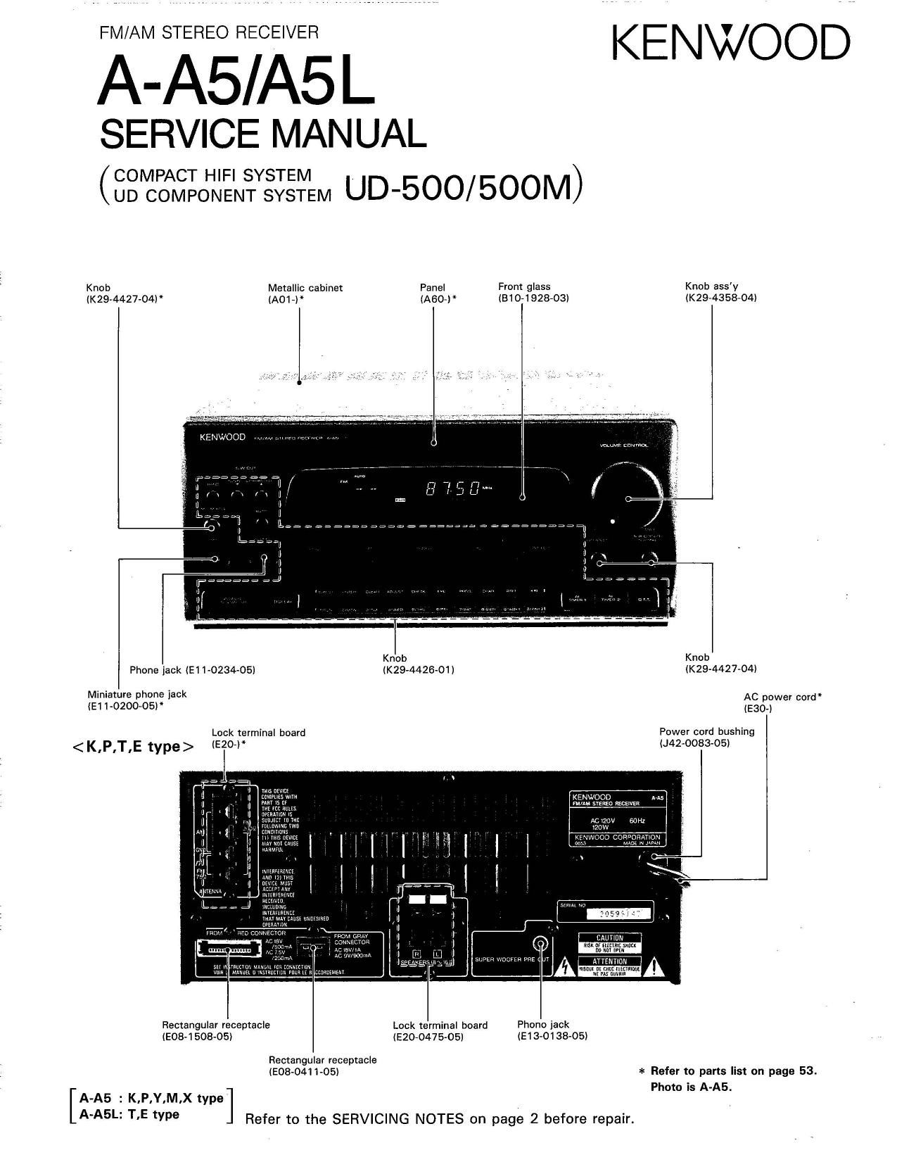
Knob Mmallic cabine From glass Knob aSSV
«(294427-044 ' (A017) ~ (810-1 92803) IK29-4358-04I

Knob Knob
Phone jack {E1 1-0234-05) (K29-4426-OI) (K29-4427-04!
Miniature phone jack AC d"
(E1 1-0200-05) (Esgjwer cor
Lock terminal board Power cord bushing
(E20») AZ-008305)

< K.P.T,E type>

m m m

Rectangular receptacie Lock terminal! board Fhano jack
(EOE-150805) (E20-0475-05) {E19-01 38-05]

Rectangular receptacle
(E08~0411-05) * Refer to parts list on page 53.
Phom is A-AS.

[A-As : K.P,Y,M,X type

5 1,5 We ] Refer to the SERVICING NOTES on page 2 before repair.

Page 2

NA-A5/A5L

CONTENTSISERVICING NOTES

Luck terminal board
(E20-0476'05)

IxENJ/OOD

Slide switch
(53172132-05)

Rectangular receptacle Rectangular receptacle

(E08~1508-05) (E58-0001705)

Contents
CONTENTS/SERVICING NOTES ...................................
ACCESSORlES...
PACKlNG .........
CONTROLS AND INDICATORS ..
DISASSEMBLY FOR REPAIR ......
BLOCK DIAGRAM .........
CIRCUIT DESCRIPTION,

N


(D-NUl-bb)

Servicing notes

(D This unit does not contain a selector IC. However, as IN-
PUT SELECTOR IC is in corporated into the graphic equaliz-
er (GE-A5), signal system goes through the graphic equalizer.
Since each speaker relay of this unit is operated according
to the data that is serially transmitted from the graphic
equalizer (GE-A5), the receiver cannot output sound alone.
To output a tuner signal to each speaker terminal, follow
the following procedures.

Procedure 1)

Direct the tuner output to the main amplifier input. Connect the
test pin on the right (lower right of the tuner board) of the main
amplifier board (X09, A/6l (Fig. 1 or 2)

Front amplifier

K,P,T,E type [ Pins 8 and 9 (Left channel)
(Fig. l) Pins 6 and 4 (Right channel)

Y,M,X type [ Pins 3 and i (Left channel)
(Fig. 2) Pins 4 and i7 (Right channel)

After turning power ON in this setting, front l. & R channels
are output.

Slide switch
(531-301m05l

Power cord bushing
(J42-0083-05)

ATTEHTlilN
I

~ AC Power ooro'
(E30-)

Phano jack

(E63»0013705)
Lock terminal board

(Em-0459705) * Refer to parts list

on page 53.

ADJUSTMENT ........................................................ 22
WlRRING DIAGRAM ...................... 25
PC BOARD (Component side view).. 27
SCHEMATIC DIAGRAM . 33
EXPLODED VIEW ......... 49
PARTS LlST ........ 53
SPECIFICATIONS. .. 68

Procedure 2)

Enter the test mode. (Hold down the CHARACTER key, and in-

sert the AC plug into the outlet.)

All fluorescent displays light.

1) Press the LD/AUX key. (The front speaker outputs sound.)

2) Press the CHARACTER key. (S.W. OUT outputs sound.)
* Normally, S.W.OUT is operated by Remote control unit.

® Be sure to use the designated part (parts no. F20-1284-05)
for the isolation of the power (final) transistor.

® Y,M,X type only.

The cooling fan of the Main board (X09) is usually rotating
at a low speed but, when the heat sink temperature rises
above 80°C, temperature assurance switch Si opens and
the (an starts high-speed rotation. When the temperature
further rises above l05°C, temperature assurance switch
82 also opens and the protection circuitry is activated to stop
the output. (To release the protection, turn power OFF. To
check the highespeed rotation operation of the fan, short-
cirouit test pOInts W67 and W92.)

Page 13

A-A5/A5L

CIRCUIT DESCRIPTION

1. Microprocessor and back-up condenser of this unit (16-bit serial transmission is supported like the UD-100l90/70, unlike
the UD-7/9 series (8 bits).)

DP-AS/MAB
I-A-As/ABL --| l- GE-AS % - X-A5 1 l'__l


/-

lo 201 @ 5V
Receiver < x09 >

mlero- + C1 90

~ . 15 pin connection cable
"\z ' l®l BUSY, ® DATA 16 em

Reference number

_|
5|
l
l
4.
I
,
'l

CXP50116 M38173M6 uPD7551SGF uFD75216AGF
V >397C| -149FP -403 ~676

2. Microprocessor initialization (reset) and test mode

A-A5/A5L GE-A5 X-AS DP-ASIMAS
RECEIVER GE DECK CD
microprocessor microprocessor microprocessor microprocessor
(X14) ICZO1 (X14) IC17 (X28) I03 (X32) IC1
CXP5011 6-3970 M38173M6-149FP [tPD7551sGF-403 uPD75216AGF-676
Baoku ca acitnr (X09) (X14) (X28)
p p 656 2200 uF 6.3V (3190 0.047 F 5.5 V C101 0047 F 5.5V .
[K,P,T,E type) None
C237 0.047 F 5.5 V
(Y,M.>< type)
Hold down the ENTER Hold down the MEMORY Turn AC off in the CRLS Turn AC off again.
Initialization (reset) key, and insert the AC plug key, and turn AC on. test mode (see below).
into the outlet.
Hold down the CHARAC- Hold down the FLAT key, Short test pin .-[>(- @, Short-clrcuiting the test
Operation TER key, and insertthe AC and insert the AC plug into and insert the AC plug into pins CN2 (1 pin and 2 pin)
plug into the outlet. the outlet. the outlet.
Test mode Remove the AC plug from Release-AC oif, Press the PAUSE key. Release»AC off
Release
the outlet.
Contents (9 All fluorescent dlsplays light. No fluorescent display.

For details, see the service manual for each model.

13