Kenwood 1070 VR Owners Manual

This is the 53 pages manual for Kenwood 1070 VR Owners Manual.
Read or download the pdf for free. If you want to contribute, please mail your pdfs to info@audioservicemanuals.com.

Page: 1 / 53
left right
Kenwood 1070 VR Owners Manual

Extracted text from Kenwood 1070 VR Owners Manual (Ocr-read)


Page 1

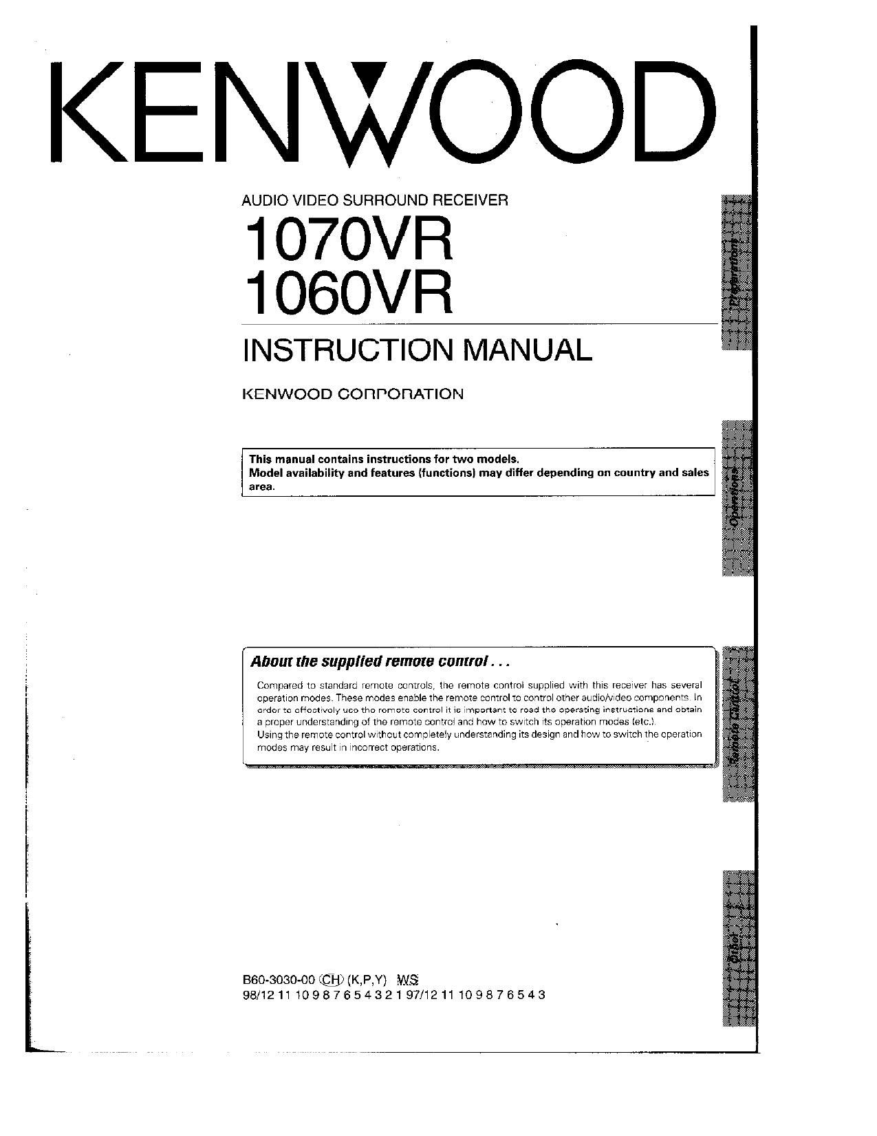
KENWOOD

AUDIO VIDEO SURROUND RECEIVER

1 O70VR
1 OGOVR

INSTRUCTION MANUAL

KENWOOD CORPORATION

This manual contains instructions for two models.
Model availability and features (functions) may differ depending on country and sales
area.

About the supplied remote control. . .

Compared to standard remote controts, the remote control suppIred with thrs receiver has several
operatlon modes These modes enable the remote control to controI other audro/vrdeo components In
order m aftectrvoly ueo tho remote control n 11: Important to read the operating inetructione and obtain
a proper understanding of the remote controI and how to swrtch Its operatron modes Ietc.)

Usmg the remote control wrlhout comptetely understanding its desrgn and how to swrtoh the operation
modes may resmt m Incorrect operations.

BGO-SO30-OO@(KP,Y) WS
98/12111098765432197/1211109876543

Page 2

Units are designed for operation as follows.

i U.S.A. and tanada.
Other countries

...... AC 120 Vanly
AC 110-110/220-240 szitchable

*AC voltage selection

The AC voItage selector SWItch on the rear panei Is set to the voltage
that prevaIls In the area to which the unit is shipped Beiore
connectlng the power cord to your AC outIet. make sure that the
setting posItIon of this switch matches your lIne voItage, It not. it
must be set to your voltage in accordance WIth the IoiIowrng direcr
tIon.

Note
Our warranty does not cover damage caused by excesswe line
voItage due to Improper setting oI the AC voitage selector swrtch,

Move walch Iever to
match your Iine voltage
With a smaII screwdnver
or other pointed tooI

Ac voltage selector switch

WARNING : TO PREVENT not on ELECTRIC 5| IOCK, DO NOT EXPOSC TI II
OR MOISTURE.

S APPLIANCE TO RAIN

Rlsx or uzcm
no Nrir mm

PERSONNEL

_AUTIOI\I CAUTION; TO REDUCE THE RISK OF ELECTRIC SHOCK, DO NOT REMOVE COVER IOR
U BACK). NO USER-SERVICEABLE PARTS INSIDE, REFER SERVICING TO QUALIFIED SERVICE

USER TO THE PRESENCE OF UNINSULATED DANGEROUSVOLTAGE WITHIN THE PRODUCTS ENCLOSURE THAT MAY BE

THE LIGHTNING FLASH WITH ARROWHEAD SYMBOL. WITHIN AN EOUILATERAL TRIANGLE, IS INTENDED TO ALERT THE
OF SUFFICIENT MAGNITUDE TO CONSTITUTE A RISK OF ELECTRIC SHOCK TO PERSONS.

APPLIANCE.

THE EXCLAMATION POINT WITHIN AN EOUILATERAL TRIANGLE IS INTENDED TO ALERT THE USER TO THE PRESENCE OF
IMPORTANT OPERATING AND MAINTENANCE (SERVICING) INSTRUCTIONS IN TIIE LITEIIATUIIE ACCOMPANYING TIII:

Unpack the unit carefuliy and make sure that all accessories are put aside so they WIII not be Iost.

Examine the unit for any possIbIIIty of shipping damage. If your unit is damaged or faiIs to operate, notify your deaIer Immediately If your
unit was shIppad to you directIy, notIfy the shipping company without delay. Only the consignee (the person or company receiving the

unit) can file a denim against the carrier for shipping damage.

We recommend that you retaIn the orIgInaI carton and packing materials Ior use shouId you transport or ship the unit in the future.

Accessories

FIvI Indoor antenna (I) AM Ioop antenna (II

A

Loop anlenna stand (I;

Remote ConerI unit (I)

Page 8

io7UVR/iUSUVR [En/Ki

Make connections as shown below.
Do not oonnoot the power aural to a wall outlet umil all unnncufions are completed.

Antenna terminal connections

0 End. In... a In." rnrA a nun... I...»

m" M . . to»: rev

AM loop antenna

The suppiied ioop antenna is for use indoors. Piace it as far as
possrble from the receiver, TV set, speaker cords and power
cord, and adjust the direction for best reception

(3

AM iooo antenna

FM indoor antenna

Use an optionsi antenna adaptor

FM outdoor antenna

FM indoor antenna FM outdoor antenna
The supplied indoor antenna is for temporary use only, For stable Lead the 75:2 coaxiai cabie connected to the FM outdoor antenna
signai reception we recommend using an outdoor antenna. into the room and connect it to the FM 7511 terminai.

Disconnect the indoor antenna when you connect one outdoors

FM DE-EMPHASIS / CHANNEL SPACE (Except for USA. and Canada)

The FM DE-EMPHASIS / CHANNEL SPACE switch on the rear \,
panel is set to the correct setting that prevails in the area to which
the unit is shipped. However. if the FM DE-EMPHASiS/CHANV
NEL SPACE setting is not matched to the area where the unit is


to be used: for instance. when you move from area 1 to area 2 or U]
vice versa, desired reception of AM / FM broadcasts Is not rm EQANNELEPMME lfli
expected. in this case, ohanqe the FM DE-EMPHASIS / CHAN- 23:2 CB: .135? 2355:
NEL SPACE setting in accordance With thearea corresponding to
the tabie. The PM DE-EMPHASIS is switched over at the same
time
A, CHANNEL FM
'When changing the setting of the FM DEsEMFHASiS / CHANNEL SPACE lreq. DE-EMPHASIS
SPACE swrtch, first dlsconnect the power cord, then reset the channel USA, Canada and FM, 100 kHz
space SWitoh, connect the power cord again, and turn the power on 1 Snmh 'Ammrzn WWW AM 10 w; 75 US
2 Other countries 231153 :2: 50 us

Page 53

:NWOO

For vaur recards
Record \he senal number, found on the back of the umt, in the spaces

designated on the warranty card, and in me space provided below. Refer
to the model and senal numbers whenever you caH upon your dearer for
iniormanon or servrce on (hrs product

Model Serral Number