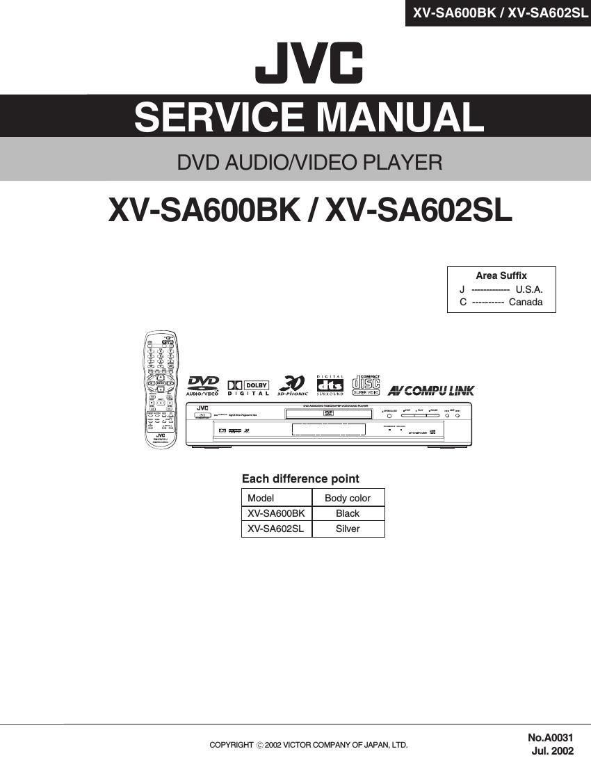
Jvc XVSA 600 BK Service Manual

This is the 84 pages manual for Jvc XVSA 600 BK Service Manual.
Read or download the pdf for free. If you want to contribute, please mail your pdfs to info@audioservicemanuals.com.

Page: 1 / 84
left right
Jvc XVSA 600 BK Service Manual

Extracted text from Jvc XVSA 600 BK Service Manual (Ocr-read)


Page 1

XV-SA600BK/XV-SA602SL 2 TABLE OF CONTENTS 1 Important Safety Precautions . . . . . . . . . . . . . . . . . . . . . . . . . . . . . . . . . . . . . . . . . . . . . . . . . . . . . . . . . . . . . 3 1.1 Safety Precautions . . . . . . . . . . . . . . . . . . . . . . . . . . . . . . . . . . . . . . . . . . . . . . . . . . . . . . . . . . . . . . . . . 3 1.2 Warning . . . . . . . . . . . . . . . . . . . . . . . . . . . . . . . . . . . . . . . . . . . . . . . . . . . . . . . . . . . . . . . . . . . . . . . . . . 3 1.3 Caution . . . . . . . . . . . . . . . . . . . . . . . . . . . . . . . . . . . . . . . . . . . . . . . . . . . . . . . . . . . . . . . . . . . . . . . . . . 3 1.4 Critical parts for safety. . . . . . . . . . . . . . . . . . . . . . . . . . . . . . . . . . . . . . . . . . . . . . . . . . . . . . . . . . . . . . . 3 1.5 Preventing static electricity . . . . . . . . . . . . . . . . . . . . . . . . . . . . . . . . . . . . . . . . . . . . . . . . . . . . . . . . . . . 4 1.6 Handling the traverse unit (optical pickup) . . . . . . . . . . . . . . . . . . . . . . . . . . . . . . . . . . . . . . . . . . . . . . . 4 1.7 Importance admistering point on the safety . . . . . . . . . . . . . . . . . . . . . . . . . . . . . . . . . . . . . . . . . . . . . . 5 1.8 Precautions for Service . . . . . . . . . . . . . . . . . . . . . . . . . . . . . . . . . . . . . . . . . . . . . . . . . . . . . . . . . . . . . . 6 2 Disassembly method . . . . . . . . . . . . . . . . . . . . . . . . . . . . . . . . . . . . . . . . . . . . . . . . . . . . . . . . . . . . . . . . . . . . 7 2.1 Main body . . . . . . . . . . . . . . . . . . . . . . . . . . . . . . . . . . . . . . . . . . . . . . . . . . . . . . . . . . . . . . . . . . . . . . . . 7 2.2 Loading assembly section . . . . . . . . . . . . . . . . . . . . . . . . . . . . . . . . . . . . . . . . . . . . . . . . . . . . . . . . . . . . 9 2.3 Traverse mechanism assembly section . . . . . . . . . . . . . . . . . . . . . . . . . . . . . . . . . . . . . . . . . . . . . . . . 13 3 Adjustment method . . . . . . . . . . . . . . . . . . . . . . . . . . . . . . . . . . . . . . . . . . . . . . . . . . . . . . . . . . . . . . . . . . . . 16 3.1 Test mode setting method . . . . . . . . . . . . . . . . . . . . . . . . . . . . . . . . . . . . . . . . . . . . . . . . . . . . . . . . . . . 16 3.2 Initialization method. . . . . . . . . . . . . . . . . . . . . . . . . . . . . . . . . . . . . . . . . . . . . . . . . . . . . . . . . . . . . . . . 16 3.3 Method of displaying version of microcomputer . . . . . . . . . . . . . . . . . . . . . . . . . . . . . . . . . . . . . . . . . . 16 3.4 Display of current value of laser . . . . . . . . . . . . . . . . . . . . . . . . . . . . . . . . . . . . . . . . . . . . . . . . . . . . . . 17 3.5 Display of jitter value . . . . . . . . . . . . . . . . . . . . . . . . . . . . . . . . . . . . . . . . . . . . . . . . . . . . . . . . . . . . . . 17 3.6 Upgrading of firmware . . . . . . . . . . . . . . . . . . . . . . . . . . . . . . . . . . . . . . . . . . . . . . . . . . . . . . . . . . . . . . 18 3.7 Display of region code . . . . . . . . . . . . . . . . . . . . . . . . . . . . . . . . . . . . . . . . . . . . . . . . . . . . . . . . . . . . . . 18 3.8 Flap adjustment of the pick-up guide shaft . . . . . . . . . . . . . . . . . . . . . . . . . . . . . . . . . . . . . . . . . . . . . . 19 3.9 Attention when pick-up is exchanged . . . . . . . . . . . . . . . . . . . . . . . . . . . . . . . . . . . . . . . . . . . . . . . . . . 20 3.10 Confirm method of operation . . . . . . . . . . . . . . . . . . . . . . . . . . . . . . . . . . . . . . . . . . . . . . . . . . . . . . . . . 21 3.11 Troubleshooting. . . . . . . . . . . . . . . . . . . . . . . . . . . . . . . . . . . . . . . . . . . . . . . . . . . . . . . . . . . . . . . . . . . 22 3.12 Check points for each error . . . . . . . . . . . . . . . . . . . . . . . . . . . . . . . . . . . . . . . . . . . . . . . . . . . . . . . . . . 23 4 Description of major ICs . . . . . . . . . . . . . . . . . . . . . . . . . . . . . . . . . . . . . . . . . . . . . . . . . . . . . . . . . . . . . . . . 26 4.1 74LCX373MTC-X(IC512,IC513) . . . . . . . . . . . . . . . . . . . . . . . . . . . . . . . . . . . . . . . . . . . . . . . . . . . . . . 26 4.2 BA5983FM-X (IC201) : 4CH Driver . . . . . . . . . . . . . . . . . . . . . . . . . . . . . . . . . . . . . . . . . . . . . . . . . . . . 27 4.3 AN8703FH-V (IC101) : Frontend processor . . . . . . . . . . . . . . . . . . . . . . . . . . . . . . . . . . . . . . . . . . . . . 28 4.4 BA6664FM-X (IC251) : 3Phase Motor Driver . . . . . . . . . . . . . . . . . . . . . . . . . . . . . . . . . . . . . . . . . . . . 29 4.5 K4S643232E-TC60(IC505):DRAM . . . . . . . . . . . . . . . . . . . . . . . . . . . . . . . . . . . . . . . . . . . . . . . . . . . . 31 4.6 MM1568AJ-X (IC801) : Video driver . . . . . . . . . . . . . . . . . . . . . . . . . . . . . . . . . . . . . . . . . . . . . . . . . . . 32 4.7 MN101C35DLD (IC701) : System controller . . . . . . . . . . . . . . . . . . . . . . . . . . . . . . . . . . . . . . . . . . . . . 33 4.8 MM1565AF-X (IC951) : 500mA Regulator . . . . . . . . . . . . . . . . . . . . . . . . . . . . . . . . . . . . . . . . . . . . . . 34 4.9 MN102L62GLH (IC401) : Unit CPU . . . . . . . . . . . . . . . . . . . . . . . . . . . . . . . . . . . . . . . . . . . . . . . . . . . 35 4.10 MN103S26EGA (IC301) : Super optical disc controller. . . . . . . . . . . . . . . . . . . . . . . . . . . . . . . . . . . . . 36 4.11 MN35505-X (IC703) : DAC . . . . . . . . . . . . . . . . . . . . . . . . . . . . . . . . . . . . . . . . . . . . . . . . . . . . . . . . . . 40 4.12 NDV8601VWA-BB(IC501):AV Decoder . . . . . . . . . . . . . . . . . . . . . . . . . . . . . . . . . . . . . . . . . . . . . . . . 41 4.13 S-93C66AFJ-X (IC451,IC510) : EEPROM . . . . . . . . . . . . . . . . . . . . . . . . . . . . . . . . . . . . . . . . . . . . . . 45 4.14 SST39VF160-7CEK (IC509) : 16M EEPROM. . . . . . . . . . . . . . . . . . . . . . . . . . . . . . . . . . . . . . . . . . . . 46 4.15 STR-G6651-F8 (IC901) : Switch regulator . . . . . . . . . . . . . . . . . . . . . . . . . . . . . . . . . . . . . . . . . . . . . . 47 4.16 TC74HC08AF-X(IC704) : 2-input and gate . . . . . . . . . . . . . . . . . . . . . . . . . . . . . . . . . . . . . . . . . . . . . . 47 5 Glossary of term and abbreviations(for AV Decoder section) . . . . . . . . . . . . . . . . . . . . . . . . . . . . . . . . . . 48

Page 2

XV-SA600BK/XV-SA602SL 3 SECTION 1 Important Safety Precautions 1.1 Safety Precautions (1) This design of this product contains special hardware and many circuits and components specially for safety purposes. For continued protection, no changes should be made to the original design unless authorized in writing by the manufacturer. Replacement parts must be identical to those used in the original circuits. Services should be performed by qualified personnel only. (2) Alterations of the design or circuitry of the product should not be made. Any design alterations of the product should not be made. Any design alterations or additions will void the manufacturers warranty and will further relieve the manufacture of responsibility for personal injury or property damage resulting therefrom. (3) Many electrical and mechanical parts in the products have special safety-related characteristics. These characteris- tics are often not evident from visual inspection nor can the protection afforded by them necessarily be obtained by using replacement components rated for higher voltage, wattage, etc. Replacement parts which have these special safety characteristics are identified in the Parts List of Service Manual. Electrical components having such feat u re s a re identified by shading on the schematics and by ( ) on the Parts List in the Service Manual. The use of a sub- stitute replacement which does not have the same safety characteristics as the recommended replacement parts shown in the Parts List of Service Manual may create shock, fire, or other hazards. (4) The leads in the products are routed and dressed with ties, clamps, tubings, barriers and the like to be separated from live parts, high temperature parts, moving parts and/or sharp edges for the prevention of electric shock and fire hazard. When service is required, the original lead routing and dress should be observed, and it should be confirmed that they have been returned to normal, after reassembling. (5) Leakage shock hazard testing) After reassembling the product, always perform an isolation check on the exposed metal parts of the product (antenna terminals, knobs, metal cabinet, screw heads, headphone jack, control shafts, etc.) to be sure the product is safe to operate without danger of electrical shock. Do not use a line isolation transformer during this check. - Plug the AC line cord directly into the AC outlet. Using a "Leakage Current Tester", measure the leakage current from each exposed metal parts of the cabinet, particu- larly any exposed metal part having a return path to the chassis, to a known good earth ground. Any leakage current must not exceed 0.5mA AC (r.m.s.). - Alternate check method Plug the AC line cord directly into the AC outlet. Use an AC voltmeter having, 1,000 ohms per volt or more sen- sitivity in the following manner. Connect a 1,500 10W resistor paralleled by a 0.15 F AC-type capacitor be- tween an exposed metal part and a known good earth ground.Measure the AC voltage across the resistor with the AC voltmeter. Move the resistor connection to each exposed metal part, particularly any exposed metal part having a return path to the chassis, and measure the AC voltage across the resistor. Now, reverse the plug in the AC outlet and repeat each measurement. Voltage measured any must not exceed 0.75 V AC (r.m.s.). This corresponds to 0.5 mA AC (r.m.s.). 1.2 Warning (1) This equipment has been designed and manufactured to meet international safety standards. (2) It is the legal responsibility of the repairer to ensure that these safety standards are maintained. (3) Repairs must be made in accordance with the relevant safety standards. (4) It is essential that safety critical components are replaced by approved parts. (5) If mains voltage selector is provided, check setting for lo- cal voltage. 1.3 Caution Burrs formed during molding may be left over on some parts of the chassis. Therefore, pay attention to such burrs in the case of pre- forming repair of this system. 1.4 Critical parts for safety In regard with component parts appearing on the silk-screen printed side (parts side) of the PWB diagrams, the parts that are printed over with black such as the resistor ( ), diode ( ) and ICP ( ) or identified by the " " mark nearby are critical for safety. When replacing them, be sure to use the parts of the same type and rating as specified by the manufacturer. (Except the JC version) Good earth groundPlace this probe on each expose d metal part. AC VOLTMETER(Having 1000 ohms/volts, or more sensitivity) 1500 10W 0.15 F AC TYPE

Page 81

XV-SA600BK/XV-SA602SL 3-16 Item Parts number Parts name Area Electrical parts list (Surround audio board) Remarks Block No. 03 A BK811 E409182-001SM GRAND TERMINAL C 838 QFLC1HJ-102Z M CAPACITOR 1000PF 5% 50V C 839 QFLC1HJ-102Z M CAPACITOR 1000PF 5% 50V C 841 QFLC1HJ-222Z M CAPACITOR 2200PF 5% 50V C 842 QFLC1HJ-222Z M CAPACITOR 2200PF 5% 50V C 843 QTE1A48-476Z E.CAPA I/M C 844 QTE1A48-476Z E.CAPA I/M C 845 QTE1C28-107Z E CAPACITOR C 846 QTE1C28-107Z E CAPACITOR C 847 QTE1C28-107Z E CAPACITOR C 848 QTE1C28-107Z E CAPACITOR C 849 QFLC1HJ-102Z M CAPACITOR 1000PF 5% 50V C 850 QFLC1HJ-102Z M CAPACITOR 1000PF 5% 50V C 851 QFLC1HJ-123Z M CAPACITOR .012MF 5% 50V C 852 QFLC1HJ-123Z M CAPACITOR .012MF 5% 50V C 853 QFLC1HJ-121Z M CAPACITOR 120PF 5% 50V C 854 QFLC1HJ-121Z M CAPACITOR 120PF 5% 50V C 855 QFLC1HJ-472Z M CAPACITOR 4700PF 5% 50V C 856 QFLC1HJ-472Z M CAPACITOR 4700PF 5% 50V C 857 QFLC1HJ-122Z M CAPACITOR 1200PF 5% 50V C 858 QFLC1HJ-122Z M CAPACITOR 1200PF 5% 50V C 859 QTE0J28-477ZE CAPACITOR C 860 QTE0J28-477ZE CAPACITOR C 863 QCZ0202-155Z ML C CAPA I/M 1.5MF C 864 QCZ0202-155Z ML C CAPA I/M 1.5MF C 866 QFN31HJ-103Z M CAPACITOR .010MF 5% 50V C 867 QFVJ1HJ-224Z MF CAPACITOR .22MF 5% 50V C 868 QTE0J28-227ZE CAPACITOR C 869 QFN31HJ-152Z M CAPACITOR 1500PF 5% 50V C 871 QFN31HJ-152Z M CAPACITOR 1500PF 5% 50V C 873 QFLC1HJ-222Z M CAPACITOR 2200PF 5% 50V C 874 QFLC1HJ-222Z M CAPACITOR 2200PF 5% 50V C 875 QTE1A48-476Z E.CAPA I/M C 876 QTE1A48-476Z E.CAPA I/M C 877 QTE1C28-107Z E CAPACITOR C 878 QTE1C28-107Z E CAPACITOR C 879 QTE1C28-107Z E CAPACITOR C 880 QTE1C28-107Z E CAPACITOR C 881 QFLC1HJ-102Z M CAPACITOR 1000PF 5% 50V C 882 QFLC1HJ-102Z M CAPACITOR 1000PF 5% 50V C 883 QFLC1HJ-123Z M CAPACITOR .012MF 5% 50V C 884 QFLC1HJ-123Z M CAPACITOR .012MF 5% 50V C 885 QFLC1HJ-472Z M CAPACITOR 4700PF 5% 50V C 886 QFLC1HJ-472Z M CAPACITOR 4700PF 5% 50V C 887 QFLC1HJ-121Z M CAPACITOR 120PF 5% 50V C 888 QFLC1HJ-121Z M CAPACITOR 120PF 5% 50V C 889 QFLC1HJ-122Z M CAPACITOR 1200PF 5% 50V C 890 QFLC1HJ-122Z M CAPACITOR 1200PF 5% 50V C 891 QTE0J28-477ZE CAPACITOR C 892 QTE0J28-477ZE CAPACITOR C 895 QCZ0202-155Z ML C CAPA I/M 1.5MF C 897 QTE0J28-227ZE CAPACITOR C 898 QFVJ1HJ-224Z MF CAPACITOR .22MF 5% 50V C 899 QFN31HJ-103Z M CAPACITOR .010MF 5% 50V C 900 QCZ0202-155Z ML C CAPA I/M 1.5MF C 902 QFLC1HJ-102Z M CAPACITOR 1000PF 5% 50V C 903 QFLC1HJ-102Z M CAPACITOR 1000PF 5% 50V C1891 QDGB1HK-102Y C CAPACITOR C1991 QDGB1HK-102Y C CAPACITOR CN711 QGF1205C1-17 CONNECTOR IC811 NJM4580L IC IC812 NJM4580L IC IC813 MN35505-X IC C M IC821 NJM4580L IC IC822 NJM4580L IC IC823 MN35505-X IC C M J 811 QNN0461-001 PIN JACK J 821 QNN0455-001 PIN JACK K 811 QQR0601-001Z FERRITE BEADS K 812 QQR0601-001Z FERRITE BEADS K 813 QQR0601-001Z FERRITE BEADS K 821 QQR0601-001Z FERRITE BEADS K 822 QQR0601-001Z FERRITE BEADS K 823 QQR0601-001Z FERRITE BEADS K 829 QQR0601-001Z FERRITE BEADS K8291 QQR0601-001Z FERRITE BEADS Q 811 2SD2144S/VW/-T TRANSISTOR Q 812 2SD2144S/VW/-T TRANSISTOR Q 821 2SD2144S/VW/-T TRANSISTOR Q 822 2SD2144S/VW/-T TRANSISTOR R 861 QRE141J-103Y C RESISTOR 10K 5% 1/4W R 862 QRE141J-103Y C RESISTOR 10K 5% 1/4W R 863 QRE141J-101Y C RESISTOR 100 5% 1/4W R 864 QRE141J-101Y C RESISTOR 100 5% 1/4W R 865 QRE141J-561Y C RESISTOR 560 5% 1/4W R 866 QRE141J-561Y C RESISTOR 560 5% 1/4W R 867 QRE141J-273Y C RESISTOR 27K 5% 1/4W R 868 QRE141J-273Y C RESISTOR 27K 5% 1/4W R 869 QRE141J-183Y C RESISTOR 18K 5% 1/4W R 870 QRE141J-183Y C RESISTOR 18K 5% 1/4W R 871 QRE141J-102Y C RESISTOR 1.0K 5% 1/4 W R 872 QRE141J-102Y C RESISTOR 1.0K 5% 1/4 W R 873 QRE141J-221Y C RESISTOR 220 5% 1/4W R 874 QRE141J-221Y C RESISTOR 220 5% 1/4W R 875 QRE141J-221Y C RESISTOR 220 5% 1/4W R 876 QRE141J-221Y C RESISTOR 220 5% 1/4W R 877 QRA14CF-7500Y MF RESISTOR 75 1/4W R 878 QRA14CF-7500Y MF RESISTOR 75 1/4W R 881 QRA14CF-7500Y MF RESISTOR 75 1/4W R 882 QRA14CF-7500Y MF RESISTOR 75 1/4W R 883 QRE141J-362Y C RESISTOR 3.6K 5% 1/4 W R 884 QRE141J-362Y C RESISTOR 3.6K 5% 1/4 W R 885 QRA14CF-3602Y MF RESISTOR 36 1/4W R 886 QRA14CF-3602Y MF RESISTOR 36 1/4W R 887 QRA14CF-1601Y MF RESISTOR 16 1/4W R 888 QRA14CF-1601Y MF RESISTOR 16 1/4W R 889 QRE141J-272Y C RESISTOR 2.7K 5% 1/4 W R 890 QRE141J-272Y C RESISTOR 2.7K 5% 1/4 W R 891 QRA14CF-1802Y MF RESISTOR 18 1/4W R 892 QRA14CF-1802Y MF RESISTOR 18 1/4W R 893 QRA14CF-1802Y MF RESISTOR 18 1/4W R 894 QRA14CF-1802Y MF RESISTOR 18 1/4W R 895 QRE141J-303Y C RESISTOR 30K 5% 1/4W R 896 QRE141J-303Y C RESISTOR 30K 5% 1/4W R 897 QRE141J-303Y C RESISTOR 30K 5% 1/4W R 898 QRE141J-303Y C RESISTOR 30K 5% 1/4W R 899 QRE141J-470Y C RESISTOR 47 5% 1/4W R 909 QRE141J-471Y C RESISTOR 470 5% 1/4W R 911 QRE141J-100Y C RESISTOR 10 5% 1/4W R 912 QRE141J-560Y C RESISTOR 56 5% 1/4W R 913 QRE141J-332Y C RESISTOR 3.3K 5% 1/4 W R 914 QRE141J-471Y C RESISTOR 470 5% 1/4W R 915 QRE141J-181Y C RESISTOR 180 5% 1/4W R 916 QRE141J-471Y C RESISTOR 470 5% 1/4W R 917 QRE141J-471Y C RESISTOR 470 5% 1/4W R 918 QRE141J-471Y C RESISTOR 470 5% 1/4W R 919 QRE141J-471Y C RESISTOR 470 5% 1/4W R 923 QRE141J-103Y C RESISTOR 10K 5% 1/4W R 924 QRE141J-103Y C RESISTOR 10K 5% 1/4W R 925 QRE141J-101Y C RESISTOR 100 5% 1/4W R 926 QRE141J-101Y C RESISTOR 100 5% 1/4W R 927 QRE141J-561Y C RESISTOR 560 5% 1/4W Item Parts number Parts name Area Remarks A