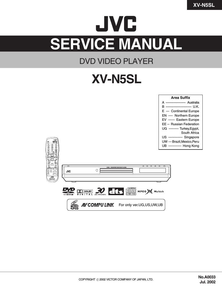
Jvc XVN 5 SL Service Manual

This is the 82 pages manual for Jvc XVN 5 SL Service Manual.
Read or download the pdf for free. If you want to contribute, please mail your pdfs to info@audioservicemanuals.com.

Page: 1 / 82
left right
Jvc XVN 5 SL Service Manual

Extracted text from Jvc XVN 5 SL Service Manual (Ocr-read)


Page 1

XV-N5SL 2 TABLE OF CONTENTS 1 Important Safety Precautions . . . . . . . . . . . . . . . . . . . . . . . . . . . . . . . . . . . . . . . . . . . . . . . . . . . . . . . . . . . . . 3 1.1 Safety Precautions . . . . . . . . . . . . . . . . . . . . . . . . . . . . . . . . . . . . . . . . . . . . . . . . . . . . . . . . . . . . . . . . . 3 1.2 Warning . . . . . . . . . . . . . . . . . . . . . . . . . . . . . . . . . . . . . . . . . . . . . . . . . . . . . . . . . . . . . . . . . . . . . . . . . . 3 1.3 Caution . . . . . . . . . . . . . . . . . . . . . . . . . . . . . . . . . . . . . . . . . . . . . . . . . . . . . . . . . . . . . . . . . . . . . . . . . . 3 1.4 Critical parts for safety. . . . . . . . . . . . . . . . . . . . . . . . . . . . . . . . . . . . . . . . . . . . . . . . . . . . . . . . . . . . . . . 3 1.5 Preventing static electricity . . . . . . . . . . . . . . . . . . . . . . . . . . . . . . . . . . . . . . . . . . . . . . . . . . . . . . . . . . . 4 1.6 Handling the traverse unit (optical pickup) . . . . . . . . . . . . . . . . . . . . . . . . . . . . . . . . . . . . . . . . . . . . . . . 4 1.7 Important for laser products . . . . . . . . . . . . . . . . . . . . . . . . . . . . . . . . . . . . . . . . . . . . . . . . . . . . . . . . . . 5 1.8 Precautions for Service . . . . . . . . . . . . . . . . . . . . . . . . . . . . . . . . . . . . . . . . . . . . . . . . . . . . . . . . . . . . . . 6 2 Disassembly method . . . . . . . . . . . . . . . . . . . . . . . . . . . . . . . . . . . . . . . . . . . . . . . . . . . . . . . . . . . . . . . . . . . . 7 2.1 Main body section . . . . . . . . . . . . . . . . . . . . . . . . . . . . . . . . . . . . . . . . . . . . . . . . . . . . . . . . . . . . . . . . . . 7 3 MECHANISM . . . . . . . . . . . . . . . . . . . . . . . . . . . . . . . . . . . . . . . . . . . . . . . . . . . . . . . . . . . . . . . . . . . . . . . . . . 10 3.1 Loading assembly section . . . . . . . . . . . . . . . . . . . . . . . . . . . . . . . . . . . . . . . . . . . . . . . . . . . . . . . . . . . 10 3.2 Traverse mechanism assembly section . . . . . . . . . . . . . . . . . . . . . . . . . . . . . . . . . . . . . . . . . . . . . . . . 14 4 Adjustment method . . . . . . . . . . . . . . . . . . . . . . . . . . . . . . . . . . . . . . . . . . . . . . . . . . . . . . . . . . . . . . . . . . . . 17 4.1 Test mode setting method . . . . . . . . . . . . . . . . . . . . . . . . . . . . . . . . . . . . . . . . . . . . . . . . . . . . . . . . . . . 17 4.2 Initialization method. . . . . . . . . . . . . . . . . . . . . . . . . . . . . . . . . . . . . . . . . . . . . . . . . . . . . . . . . . . . . . . . 17 4.3 Method of displaying version of microcomputer . . . . . . . . . . . . . . . . . . . . . . . . . . . . . . . . . . . . . . . . . . 17 4.4 Display of current value of laser . . . . . . . . . . . . . . . . . . . . . . . . . . . . . . . . . . . . . . . . . . . . . . . . . . . . . . 18 4.5 Display of jitter value . . . . . . . . . . . . . . . . . . . . . . . . . . . . . . . . . . . . . . . . . . . . . . . . . . . . . . . . . . . . . . 18 4.6 Upgrading of firmware . . . . . . . . . . . . . . . . . . . . . . . . . . . . . . . . . . . . . . . . . . . . . . . . . . . . . . . . . . . . . . 19 4.7 Display of region code . . . . . . . . . . . . . . . . . . . . . . . . . . . . . . . . . . . . . . . . . . . . . . . . . . . . . . . . . . . . . . 19 4.8 Flap adjustment of the pick-up guide shaft . . . . . . . . . . . . . . . . . . . . . . . . . . . . . . . . . . . . . . . . . . . . . . 20 4.9 Attention when pick-up is exchanged . . . . . . . . . . . . . . . . . . . . . . . . . . . . . . . . . . . . . . . . . . . . . . . . . . 21 4.10 Confirm method of operation . . . . . . . . . . . . . . . . . . . . . . . . . . . . . . . . . . . . . . . . . . . . . . . . . . . . . . . . . 22 4.11 Troubleshooting. . . . . . . . . . . . . . . . . . . . . . . . . . . . . . . . . . . . . . . . . . . . . . . . . . . . . . . . . . . . . . . . . . . 23 4.12 Check points for each error . . . . . . . . . . . . . . . . . . . . . . . . . . . . . . . . . . . . . . . . . . . . . . . . . . . . . . . . . . 24 5 Description of major ICs . . . . . . . . . . . . . . . . . . . . . . . . . . . . . . . . . . . . . . . . . . . . . . . . . . . . . . . . . . . . . . . . 27 5.1 74LCX373MTC-X(IC512,IC513) . . . . . . . . . . . . . . . . . . . . . . . . . . . . . . . . . . . . . . . . . . . . . . . . . . . . . . 27 5.2 BA5983FM-X (IC201) : 4CH Driver . . . . . . . . . . . . . . . . . . . . . . . . . . . . . . . . . . . . . . . . . . . . . . . . . . . . 28 5.3 AN8703FH-V (IC101) : Frontend processor . . . . . . . . . . . . . . . . . . . . . . . . . . . . . . . . . . . . . . . . . . . . . 29 5.4 BA6664FM-X (IC251) : 3Phase Motor Driver . . . . . . . . . . . . . . . . . . . . . . . . . . . . . . . . . . . . . . . . . . . . 30 5.5 K4S641632F-TC75 (IC506) :CMOS SDRAM . . . . . . . . . . . . . . . . . . . . . . . . . . . . . . . . . . . . . . . . . . . . 32 5.6 MN101C57DLR(IC1):System controller . . . . . . . . . . . . . . . . . . . . . . . . . . . . . . . . . . . . . . . . . . . . . . . . 33 5.7 MM1565AF-X (IC951) : 500mA Regulator . . . . . . . . . . . . . . . . . . . . . . . . . . . . . . . . . . . . . . . . . . . . . . 34 5.8 MN102L62GLF3 (IC401) : Unit CPU . . . . . . . . . . . . . . . . . . . . . . . . . . . . . . . . . . . . . . . . . . . . . . . . . . . 35 5.9 MN103S26EGA (IC301) : Super optical disc controller . . . . . . . . . . . . . . . . . . . . . . . . . . . . . . . . . . . . 36 5.10 MN35505-X (IC703) : DAC. . . . . . . . . . . . . . . . . . . . . . . . . . . . . . . . . . . . . . . . . . . . . . . . . . . . . . . . . . 40 5.11 NDV8601VWA-BE(IC501):AV Decoder . . . . . . . . . . . . . . . . . . . . . . . . . . . . . . . . . . . . . . . . . . . . . . . . 41 5.12 S-93C66AFJ-X (IC451,IC510) : EEPROM . . . . . . . . . . . . . . . . . . . . . . . . . . . . . . . . . . . . . . . . . . . . . . 45 5.13 SST39VF160-7CEK (IC509) : 16M EEPROM . . . . . . . . . . . . . . . . . . . . . . . . . . . . . . . . . . . . . . . . . . . 46 5.14 STR-G6551-F8 (IC901) : Switch regulator . . . . . . . . . . . . . . . . . . . . . . . . . . . . . . . . . . . . . . . . . . . . . . 47 5.15 TC74HC08AF-X(IC704) : 2-input and gate . . . . . . . . . . . . . . . . . . . . . . . . . . . . . . . . . . . . . . . . . . . . . . 47 6 Glossary of term and abbreviations(for AV Decoder section) . . . . . . . . . . . . . . . . . . . . . . . . . . . . . . . . . . 48

Page 2

XV-N5SL 3 SECTION 1 Important Safety Precautions 1.1 Safety Precautions (1) This design of this product contains special hardware and many circuits and components specially for safety purposes. For continued protection, no changes should be made to the original design unless authorized in writing by the manufacturer. Replacement parts must be identical to those used in the original circuits. Services should be performed by qualified personnel only. (2) Alterations of the design or circuitry of the product should not be made. Any design alterations of the product should not be made. Any design alterations or additions will void the manufacturers warranty and will further relieve the manufacture of responsibility for personal injury or property damage resulting therefrom. (3) Many electrical and mechanical parts in the products have special safety-related characteristics. These characteris- tics are often not evident from visual inspection nor can the protection afforded by them necessarily be obtained by using replacement components rated for higher voltage, wattage, etc. Replacement parts which have these special safety characteristics are identified in the Parts List of Service Manual. Electrical components having such feat u re s a re identified by shading on the schematics and by ( ) on the Parts List in the Service Manual. The use of a sub- stitute replacement which does not have the same safety characteristics as the recommended replacement parts shown in the Parts List of Service Manual may create shock, fire, or other hazards. (4) The leads in the products are routed and dressed with ties, clamps, tubings, barriers and the like to be separated from live parts, high temperature parts, moving parts and/or sharp edges for the prevention of electric shock and fire hazard. When service is required, the original lead routing and dress should be observed, and it should be confirmed that they have been returned to normal, after reassembling. (5) Leakage shock hazard testing) After reassembling the product, always perform an isolation check on the exposed metal parts of the product (antenna terminals, knobs, metal cabinet, screw heads, headphone jack, control shafts, etc.) to be sure the product is safe to operate without danger of electrical shock. Do not use a line isolation transformer during this check. - Plug the AC line cord directly into the AC outlet. Using a "Leakage Current Tester", measure the leakage current from each exposed metal parts of the cabinet, particu- larly any exposed metal part having a return path to the chassis, to a known good earth ground. Any leakage current must not exceed 0.5mA AC (r.m.s.). - Alternate check method Plug the AC line cord directly into the AC outlet. Use an AC voltmeter having, 1,000 ohms per volt or more sensitivity in the following manner. Connect a 1,500 ohm 10W resistor paralleled by a 0.15 µF AC-type capacitor between an exposed metal part and a known good earth ground. Measure the AC voltage across the resistor with the ACvoltmeter. Move the resistor connection to each exposed metal part, particularly any exposed metal part having a return path to the chassis, and measure the AC voltage across the resistor. Now, reverse the plug in the AC outlet and repeat each measurement. Voltage measured any must not exceed 0.75 V AC (r.m.s.). This corresponds to 0.5 mA AC (r.m.s.). 1.2 Warning (1) This equipment has been designed and manufactured to meet international safety standards. (2) It is the legal responsibility of the repairer to ensure that these safety standards are maintained. (3) Repairs must be made in accordance with the relevant safety standards. (4) It is essential that safety critical components are replaced by approved parts. (5) If mains voltage selector is provided, check setting for lo- cal voltage. 1.3 Caution Burrs formed during molding may be left over on some parts of the chassis. Therefore, pay attention to such burrs in the case of pre- forming repair of this system. 1.4 Critical parts for safety In regard with component parts appearing on the silk-screen printed side (parts side) of the PWB diagrams, the parts that are printed over with black such as the resistor ( ), diode ( ) and ICP ( ) or identified by the " " mark nearby are critical for safe- ty. When replacing them, be sure to use the parts of the same type and rating as specified by the manufacturer. (Except the JC version)

Page 56

XV-N5SL 2-7 Audio signal FW903 K518 IC509EP701 K515R510 C500 K564 CN511 IC522 IC510 IC523K520C579 R604 R602 C619C504 FW901 IC512 TP848 IC513C505 R512K566 K567 C508 K569 K570 K571 K572 K573 K574 K575 K576 K577 C503 K582 K561 K586 C590 C591 C593 R601C594 K579 K563 K560C502 R511L503 L502 C595 C592 C992 C569 C554 CN501 R502 R521SW501 K519 C621C620 R655 QUM104-16DGZ4 +12V NQR0007-002X-12V SST39VF160-9CEKQNZ0136-001Z AGND DGNDDGND SGND NQR0007-002X DGND0 100/10 NQR0007-002XQGF1016C1-27 D3.3V 74LCX32MTC-X DGND S-93C66AFJ-XDGND NC7SZ125P5-XNQR0007-002XNI D3.3V NI NI 0.1/16100/10 QUM108-14DGZ4 74LCX373MTC-X DGNDD5V 74LCX373MTC-X100/10 3.3KS5V NQR0007-002X NQR0007-002X 100/10 NQR0007-002X NQR0007-002X NQR0007-002X NQR0007-002X NQR0007-002X NQR0007-002X NQR0007-002X NQR0007-002X NQR0007-002X M5V 100/10 NQR0007-002X NQR0007-002X NQR0007-002X 0.1 0.1 MGNDM9V 0.1 NI0.1 NQR0007-002X NQR0007-002X D3.3V NQR0007-002X 100/10 S3.3V 01 1 D3.3V 0.10.1 0.1/16 D5V D3.3V 0.1/16 0.1/16 NI NI 10KNI NQR0007-002X NINI 0 DISCSTP3VS1OUT SSPIN1A P.ON AVCOMP SSPOUT1P.ON DISCSETAVCOMP SSPCLK1B TOPEN TCLOSE CLP /LMMUTE FLCS3V FLINT SPDIFSWOPEN SWUPDNINT/PROG CLP AOUT0RGB NTB LRCLKS1OUT DCLK BCK DDATAPROINT DAC1CS AOUT1 DAC2CS AOUT2 192kCPURST DAC0CS LRMUTEMUTE DAC0CS DAC2CS RGB FLINT SWMUTEFLCS3V DAC1CS X6 NTB DACDENA PROINT INT/PROGNTB RGB LADD16 FCS- AD15 AD7 LA0 AD14 AD6 AD13 AD5 AD12 AD4 AD11 LADD15 LADD14 LADD13 LADD12 LADD11 LADD10 LADD9 LADD8 LADD19 ACK LADD18 LADD17 LADD7 LADD6 LADD5 LADD4AD3 AD10 AD2 AD9 AD1 AD8 AD0 LA3 LA1AD11 AD10 AD9 AD8 LADD11 LADD10 LADD9 LADD8AD12 AD13 AD15 AD14 LADD15 LADD14AD19 LADD13 LADD12 RD-LADD7 LADD18 LADD17 LADD19 AD7 AD18 AD17 LADD6 LADD5 LADD4 LADD16 AD6 AD5 AD4 AD16 PWE0 LA2 LHLDLHLDA AD1 AD3 AD5 AD6 AD7 AD8 AD10 AD11 AD12 AD13 AD14 AD15 PWE0 LA2 LA0 RD- AD16 AD17 AD19 AD21 AD22 AD23 AD24 AD26 AD28 AD30 PWE3 SCLK PWE1 AD31 AD29 AD27 AD25 AD20 AD18 PWE2 AD9 LA1 LA3 AD4 AD0 ACK PCS0ALE AD2ALE ALE SSPIN1A SSPCLK1BFCS- PCS0 BUSY DISCSET3V DISCSETSRST SSPOUT1 SSPIN1 RCK SSPCLK1 DACDENA DDATA DCLK Flash ROM section TO SHEET 2 TO SHEET 2 TO SHEET 2 TO SHEET 1TO JT911,JT912 SHEET 7 TO JT913 SHEET 7 TO SHEET 4 TO CN1 SHEET 6 TO SHEET 5 SHEET 3