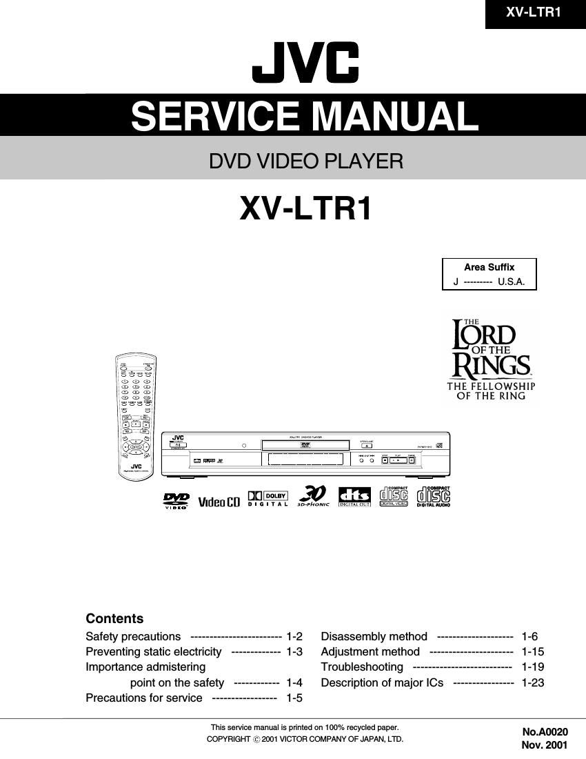
Jvc XVLTR 1 Service Manual

This is the 72 pages manual for Jvc XVLTR 1 Service Manual.
Read or download the pdf for free. If you want to contribute, please mail your pdfs to info@audioservicemanuals.com.

Page: 1 / 72
left right
Jvc XVLTR 1 Service Manual

Extracted text from Jvc XVLTR 1 Service Manual (Ocr-read)


Page 1

XV-LTR1

JVB

SERVICE MANUAL

DVD VIDEO PLAYER

XV-LTR1

Area Suffix
J --------- U.S.A.

THE

OF THE

RINGS.

THE FELLOWSHIP

OF THE RING
l ,,,,,,,,,,,,,, t l 6: WE] 7
m m an pit-w 3:24PM E31 $5?
Contents
Safety precautions ------------------------ 1-2 Disassembly method .................... 1-6
Preventing static electricity ------------- 1-3 Adjustment method ...................... 1-15
Importance admistering Troubleshooting .......................... 1-19
point on the safety ------------ 1-4 Description of major ICs ---------------- 1-23
Precautions for service ----------------- 1-5
This service manual is printed on 100% recycled paper. N0 A0020

COPYRIGHT © 2001 VICTOR COMPANY OF JAPAN, LTD.

Nov. 2001

Page 2

XV-LTR1

-Safety Precautions

1. This design of this product contains special hardware and many circuits and components specially for safety
purposes. For continued protection, no changes should be made to the original design unless authorized in
writing by the manufacturer. Replacement parts must be identical to those used in the original circuits. Services
should be performed by qualified personnel only.

2. Alterations of the design or circuitry of the product should not be made. Any design alterations of the product
should not be made. Any design alterations or additions will void the manufacturers warranty and will further
relieve the manufacture of responsibility for personal injury or property damage resulting therefrom.

3. Many electrical and mechanical parts in the products have special safety-related characteristics. These
characteristics are often not evident from visual inspection nor can the protection afforded by them necessarily
be obtained by using replacement components rated for higher voltage, wattage, etc. Replacement parts which
have these special safety characteristics are identified in the Parts List of Service Manual. Electrical
components having such features are identified by shading on the schematics and by (/t\,) on the Parts List in
the Service Manual. The use of a substitute replacement which does not have the same safety characteristics
as the recommended replacement parts shown in the Parts List of Service Manual may create shock, fire, or
other hazards.

4. The leads in the products are routed and dressed with ties, clamps, tubings, barriers and the like to be
separated from live parts, high temperature parts, moving parts and/or sharp edges for the prevention of
electric shock and fire hazard. When service is required, the original lead routing and dress should be
observed, and it should be confirmed that they have been returned to normal, after reassembling.

5. Leakage current check (Electrical shock hazard testing)

After reassembling the product, always perform an isolation check on the exposed metal parts of the product

(antenna terminals, knobs, metal cabinet, screw heads, headphone jack, control shafts, etc.) to be sure the

product is safe to operate without danger of electrical shock.

Do not use a line isolation transformer during this check.

0 Plug the AC line cord directly into the AC outlet. Using a Leakage Current Tester", measure the leakage
current from each exposed metal parts of the cabinet, particularly any exposed metal part having a return
path to the chassis, to a known good earth ground. Any leakage current must not exceed 0.5mA AC (r.m.s.).

. Alternate check method
Plug the AC line cord directly into the AC outlet. Use an AC voltmeter having, 1,000 ohms per volt or more
sensitivity in the following manner. Connect a 1,500 Q10W resistor paralleled by a 0.1 51.1 F AC-type capacitor

between an exposed metal part and a known good earth ground. AC VOLTMETER
Measure the AC voltage across the resistor with the AC a (Having1000
voltmeter. ohms/volts,

Move the resistor connection to each exposed metal part, c more sens'W'W)

particularly any exposed metal part having a return path to
the chassis, and measure the AC voltage across the resistor. 0'15: AC TYPE

Now, reverse the plug in the AC outlet and repeat each -"| Placehis
measurement.IVoltage measured any must not exceed 0.75 V W . ~ ggiieeigosed
AC (r.m.s.). This corresponds to 0.5 mA AC (r.m.s.). 15009 10W metal part.
Good earth ground
- Warning A CAUTION
1.This equipment has been designed and manufactured to meet international safety standards. Burrs formed during molding may

2. it is the legal responsibility of the repairer to ensure that these safety standards are maintained. be left over on some parts of the
3. Repairs must be made in accordance with the relevant safety standards.
4. It is essential that safety critical components are replaced by approved parts. such burrs in the case of

5. If mains voltage selector is provided, check setting for local voltage. preforming repair of this system.

chassis. Therefore, pay attention to

In regard with component parts appearing on the silk-screen printed side (parts side) of the PWB diagrams, the
parts that are printed over with black such as the resistor (-), diode (h) and ICP (Q) or identified by the (N
mark nearby are critical for safety.

When replacing them, be sure to use the parts of the same type and rating as specified by the manufacturer.
(Except the J and C version)

Page 20

XV-LTR1

Check points for each error
(1) Spindle start error

1.Defective spindle motor

*Are there several ohms resistance between each pin of CN201 "5-6","6-7","5-7"?
(The power supply is turned off and measured.)

*ls the sign wave of about 100mVp-p in the voltage had from each terminal?
[CN201"9"(H1-),"10"(H1+),"11"(H2-),"12"(H2+),"13"(H3-),"14"(H3+)]

2.Defective spindle motor driver (|0251)

*Has motor drive voltage of a sine wave or a rectangular wave gone out to each terminal(SM1~3)
of CN201"5,6,7" and |0251"2,4,7"?

*ls FG pulse output from the terminal of |0251"24"(FG) according to the rotation of the motor?
*Is it "L(about 0.9V)" while terminal of |0251"15"(VH) is rotating the motor?
3.Has the control signal come from servo IC or the microcomputer?

*ls it "L" while the terminal of |0251"18"(SBRK) is operating?
Is it "H" while the terminal of |C251"23"(/SPMUTE) is operating?

*ls the control signal input to the terminal of |0251"22"(EC)?
(changes from VHALF voltage while the motor is working.)

*ls the VHALF voltage input to the terminal of |0251"21"(ECR)?
4.|s the FG signal input to the servo IC?

*ls FG pulse input to the terminal of |030169"(FG) according to the rotation of the motor?

(2) Disc Detection, Distinction error (no disc, no RFENV)

* Laser is defective.
* Front End Processor is defective (|C101).
* APC circuit is defective. 0101,0102.
* Pattern is defective. Lines for CN101 - A|| patterns which relate to pick-up and patterns between |C101
* |C101 For signal from |C101 to |CBO1, is signal output from |C101 "20" (ASOUT) and
|C101 "41"(RFENV) and |C101 "22" (FEOUT)?

1 -20

Page 24

XV-LTR1

I BA5983FM-X (ICZO1) : 4CH Driver

1.B|ock diagram

Lie ma 1»

Vcc

+ |

+ I

10k

10k

Vcc

STAND BY
CH4

77

10k

+ I

STAND BY
CH1/2/3

ILI

2.Pin function

,_I
Iii

|_
Iii

iii

M

L: High impedance

Pin No. Symbol I/O Description Pin No. Symbol I/O Description
1 BIAS IN I Input for Bias-amplifier 15 VO4(+) 0 Non inverted output of CH4
2 OP|N1(+) I Non inverting input for CH1 OP-AMP 16 VO4(-) O Inverted output of CH4
3 OP|N1(-) I Inverting input for CH1 OP-AMP 17 VO3(+) 0 Non inverted output of CH3
4 OPOUT1 0 Output for CH1 OP-AMP 18 VO3(-) O Inverted output of CH3
5 OP|N2(+) I Non inverting input for CH2 OP-AMP 19 Pochc2 - Vcc for CH3/4 power block
6 OP|N2(-) I Inverting input for CH2 OP-AMP 20 STBY2 I Input for CM stand by control
7 OPOUT2 0 Output for CH2 OP-AMP 21 GND - Substrate ground
8 GND - Substrate ground 22 OPOUT3 0 Output for CH3 OP-AMP
9 STBY1 Input for CH1/2/3 stand by control 23 OP|N3(-) I Inverting input for CH3 OP-AMP
10 Pochc1 - Vcc for CH1/2 power block 24 OPIN3(+) I Non inverting input for CH3 OP-AMP
11 V02(-) 0 Inverted output of CH2 25 OPOUT4 0 Output for CH4 OP-AMP
12 vo2(+) 0 Non inverted output of CH2 26 OPIN4(-) I Inverting input tor CH4 OP-AMP
13 vo1 .) 0 Inverted output of CH1 27 OPIN4(+) I Non inverting input for CH4 OP-AMP
14 vo1(+) 0 Non inverted output of CH1 28 Prchc - Vcc for pre block
I 74VHCO0MTC-X (IC455,|0503) : 2-input nand gate
1.Pin layout 2.Truth table
\J
1A 1 E :J 14 vcc A B Y
18 2 [E j 13 4A L L H
1Y 3 E E] 12 48 L H H
2A 4 11 4Y
E j H L H
23 5 E j 10 3A
H H L
2v 6 E i] 9 38

GND

1 -24

7E

18 av

(TOP VIEW)

Page 43

2.Pin function (ZlVA-4.1-PA2 : 5/5)

Pin No. Symbol l/O Description

170 DVD-DATA7/CDG-SCLK | DVD parallel compressed data from DVD DSP. or CD-G clock indicating
sub code data clock input or output

171 VDACK | In synchronous mode, bitstream data acknowledge. Asserted when DVD
data is valid.Polarity is programmable

172 VREQUEST O Bitstream request

173 VSTROBE l Bitstream strobe

174 ERROR l Error in input data

175 VDD - Power supply terminal 3.3V

176 RESERVED l Tie to VSS orVDD_3.3 as specified in table 1

177 VDD - Power supply terminal 3.3V

178 VSS - Connect to ground

179 NC - Non connect

180 RESERVED l Tie to VSS orVDD_3.3 as specified in table 1

181 NC - Non connect

182 HADDRO | Host addressbus. 3-bit address bus selects one of eight host interface registers

183 HADDR1 | Host addressbus. 3-bit address bus selects one of eight host interface registers

184 HADDRZ | Host addressbus. 3-bit address bus selects one of eight host interface registers

185 RESERVED l Tie to VSS orVDDfi3.3 as specified in table 1

186 RESERVED l Tie to VSS orVDD_3.3 as specified in table 1

187 RESERVED l Tie to VSS orVDD_3.3 as specified in table 1

188 VSS - Connect to ground

189 VDD - Power supply terminal 2.5V

190 RESERVED l Tie to VSS orVDD_3.3 as specified in table 1

191 VSS - Connect to ground

192 VDD - Power supply terminal 3.3V

193 RESERVED l Tie to VSS orVDD_3.3 as specified in table 1

194 RESERVED l Tie to VSS orVDD_3.3 as specified in table 1

195 RESERVED l Tie to VSS orVDD_3.3 as specified in table 1

196 RESERVED l Tie to VSS orVDD_3.3 as specified in table 1

197 HDATA7 I/O The 8-bit bi-derectional host data through which the host writes data to
the decoder code.

198 VSS - Connect to ground

199 HDATA6 l/O The 8-bit bi-derectional host data through which the host writes data to
the decoder code.

200 HDATA5 |/O The 8-bit bi-derectional host data through which the host writes data to
the decoder code.

201 HDATA4 l/O The 8-bit bi-derectional host data through which the host writes data to
the decoder code.

202 HDATAS l/O The 8-bit bi-derectional host data through which the host writes data to
the decoder code.

203 HDATA2 l/O The 8-bit bi-derectional host data through which the host writes data to
the decoder code.

204 VDD - Power supply terminal 3.3V

205 VSS - Connect to ground

206 HDATA1 l/O The 8-bit bi-derectional host data through which the host writes data to
the decoder code.

207 HDATAO I/O The 8-bit bi-derectional host data through which the host writes data to
the decoder code.

208 CS l Host chip select input

XV-LTR1

1 -43