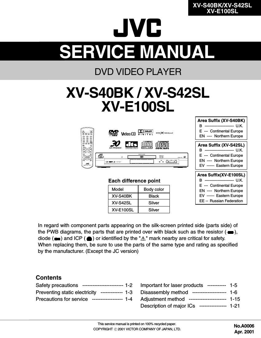
Jvc XVE 100 SL Service Manual

This is the 50 pages manual for Jvc XVE 100 SL Service Manual.
Read or download the pdf for free. If you want to contribute, please mail your pdfs to info@audioservicemanuals.com.

Page: 1 / 50
left right
Jvc XVE 100 SL Service Manual

Extracted text from Jvc XVE 100 SL Service Manual (Ocr-read)


Page 1

2-1 XV-S40BK/XV-S42SL XV-E100SL FEP (Front end processor) IC101 4CH Driver IC271 SPINDLE MOTOR DRIVER IC251 ODC (Optical disc controller) IC301 IC311 ZIVA WAIT OSCI/O X401 EPROM IC403 Unit CPU IC401 ADSC (Digital servo controller) IC201 16M ROM IC402 CN101 CN502 CN503 T1CD T2CD F1CD F2CD TR TC TD TA F2DVD F1DVD T+ T- F+ F- TDOFS FODRV TRDRV TRSDRV BDO OFTR TGBAL TBAL TE RFENV FBAL FE TG AS ARF+ ARF- TESTSG JLINEFEPEN CPSCK SDOUT SLEEP CDDET1 CDDET2 PLLOK DAT0~3 ADSCEN CIRCEN CPSCK SDOUT ADSCIRQ /WR /RD /WR /RD STD0~7 WAITODC WAITDEC WAIT DECIRQ CPUA1~20 CPUD0~7 CPUA0~2 LSIRST AV DECODER IC501 27MHz IC502 IC503 16M SDRAM IC505 16M SDRAM IC504 SYSCLK DA-IEC C/R/V Y/B/U CVBS/G/Y CVBS DA_DATA1 TO CN701 SHEET 4 TO CN961 SHEET 2 FROM EXL-V7-1 FROM EXL-V7-1 FROM FLM-J1-1 LVB10226-A1 CPUD0~7 EPDO EPDI EPSK EPCSTX 85 IC312 59 60 IC321 IC322 CPUD0~7 CPUA0~17 U2SDT S2UDT SCLKO REQ BUSY CPURST CN201 CN202 V+5V Block diagrams DVD Servo control & AV decoder section(SHEET 5,6) FM+ FM- LM+ LM- VH SM1~3 H1+~H3+ H1-~H3- SBRK SPMUTE FG DRVMUTE SWOPEN SWUPDN

Page 2

2-2 XV-S40BK/XV-S42SL XV-E100SL TO FW801 SHEET 1 TO FW802 SHEET 1 TO CN503 SHEET 6 SYSTEM CONTROLLER IC701RESET IC702 OSC X701(8MHz) DAC IC703 DAC CONTROL LPF IC741,IC751 OPTICAL DIGITAL OUT J703 ANALOG AUDIO OUT MUTE Q791 Q743,Q753 Q744, Q754 D791,D792 MUTE OPTICAL DIGITAL OUT -12V +12V TO SHEET 2 TO SHEET 3 CN703 CN702 CN701 LEA10016-A1 P.MUTE RESET POWERSW STANDBYIND REMO AIN0 AIN2 DA_DATA1U2SDT S2UDT SCLK REQ BUSY CPURST SWOPEN SWUPDNB5V TX J702 AV COMPULINK AV COMPULINK Q709 AVCI, AVCO AUDIO_R AUDIO_L IC704 D3.3V COAXIAL DIGITAL OUT System control & audio output section(SHEET 4) FL Display & Operation switch section(SHEET 1) S1~S24 1G~13G TO SHEET 1 OUT1C OUT1D OUT2C OUT2D FL DISPLAY DI801 TO SHEET 4 TO SHEET 2S1~S24 1G~13G B5V F- F+OPERATION SWITCH S831~S835 S821 AIN0 AIN2TO CN703 SHEET 4 FW801 REMOTE CONTROL IC801 POWER SWITCH S801 STANDBY INDICATOR D801 REMO TO CN702 SHEET 4 FW802 POWERSW STANDBYIND FW803 Rch Lch

Page 24

XV-S40BK/XV-S42SL/XV-E100SL 1-13 Remove the screw I attaching the T spring (S) and the shaft holder. Remove also the plate. 1. Removing the pickup (See Fig.16 and 17) Remove the screw K attaching the shaft holder. Remove the shaft. 1. 2. Removing the shaft holder / shaft (See Fig.18) When reattaching, make sure that the T spring (S) presses the shaft. ATTENTION: Pull out the part l of the shaft upward. Move the part m in the direction of the arrow and detach from the spindle base. Disengage the joint n of the pickup and the shaft in the direction of the arrow. Pull out the shaft from the pickup. Remove the two screws J attaching the actuator. Disengage the joint of the actuator and the lead spring. Pull out the lead spring. 2. 3. 4. 5. 6. The spring must be under the shaft when you install pick-up. Fig.16 Fig.17 Fig.18 T spring (S)PlateJoint nPickup Part m Shaft holder Part l I Shaft Shaft SpringPick-upPickupLead springActuator J Actuator Lead spring Shaft Shaft holder K