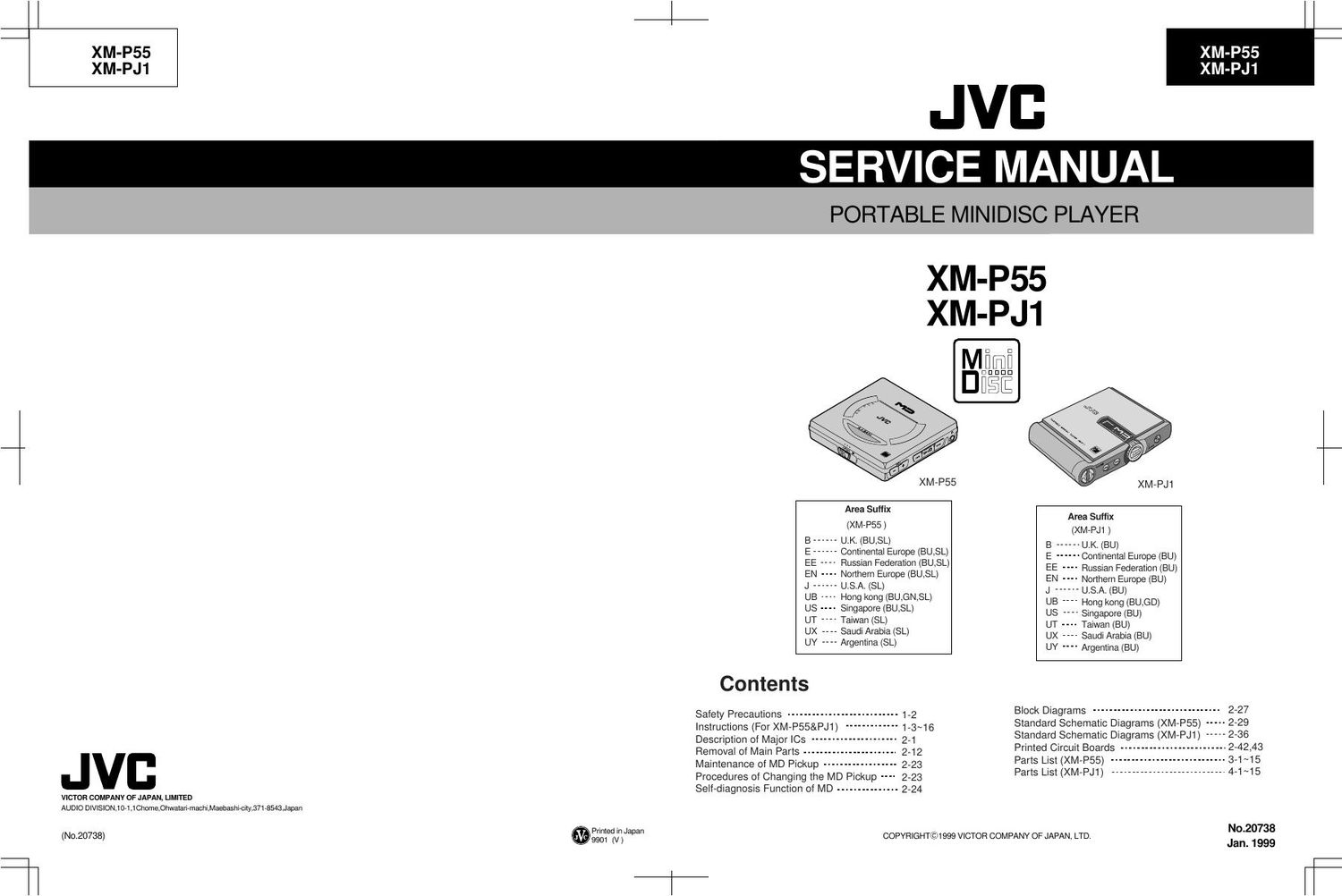
Jvc XMPJ 1 Service Manual

This is the 78 pages manual for Jvc XMPJ 1 Service Manual.
Read or download the pdf for free. If you want to contribute, please mail your pdfs to info@audioservicemanuals.com.

Page: 1 / 78
left right
Jvc XMPJ 1 Service Manual

Extracted text from Jvc XMPJ 1 Service Manual (Ocr-read)


Page 1

1-24-15 XM-P55 XM-PJ1 XM-P55 XM-PJ1 CAUTION CAUTION Burrs formed during molding may be left over on some parts of the chassis. Therefore, pay attention to such burrs in the case of preforming repair of this system. Safety Precaution Please use enough caution not to see the beam directly or touch it in case of an adjustment or operation check. Packing Parts List Accessories Parts List

Page 2

XM-P55 XM-PJ1 2-1 37 38 PEAK RF 39 RFAGC 40 AGCI 41 COMPO 42 COMPP 43 ADDC 44 OPO 45 OPN 46 RFO 47 MORFI 48 1 2 MORFO 24 23Vcc 3TADJ 22 EQADJ 21 VREF 20 F0CNT 19 XSTBY 18 XLAT 17 SCLK 16 SWDT 15 TEMP R 14 TEMP I 13 GND I J 3 VC 4A 5B 6C 7D 8E 9F 10 PD 11 APC 12 APCREF 36 35 BOTM ABCD 34FE 33AUX 32ADFG 31ADAGC 30ADIN 29ADFM 28SE 27CSLED 26TE 25WBLADJ Peak, Bottom DetectorAGC, EQ USER Comp USER OP Amp RF Amp 3T Detector ABCD Amp I-V Amp APCTEMP Amp MUX FE AmpADIP Amp TE/SE Amp CPU Command I/F CXA2523AR(IC310):MD RF & Servo 1.Block Diagram 2.Pin Function 1 2 3 4 5 6 7 8 9 10 11 12 13 14 15 16 17 18 19 20I-V converted RF signal I input. I-V converted RF signal J input. Vcc/2 voltage output. A current input for main beam servo signal. B current input for main beam servo signal. C current input for main beam servo signal. D current input for main beam servo signal. E current input for side beam servo signal. F current input for side beam servo signal. Reflection light quantity monitor signal input. Laser APC output. Reference voltage input for the laser power intensity setting. Connect to GND. Connects the temperature sensor. Connects the temperature sensor. outputs the reference voltage. Data input for microcomputer serial interface. Shift clock input for microcomputer serial interface. Latch signal input for microcomputer serial interface.Latched when low. Standby setting pin. Normal operation when high Standby when low. Internal current source setting pin. I J VC A B C D E F PD APC APCREF GND TEMPI TEMP R SWDT SCLK XLAT XSTBY F0CNTI I O I I I I I I I O I - I I I I I I I Pin No. Symbol I/OFunction Description of Major ICs

Page 8

XM-P55 XM-PJ1 2-7 HD6433045SV14X (IC501): Beams Microcomputer Address bus Data bus (upper level) Data bus (lower level) Por t 3 Por t 6 Por t 8 Por t 5 Por t 2 Bus Controller Por t 1 Por t 9 Clock generator Por t 4 Interrupt controller ROM Mask ROM PROM Flash memory 16 bits integrated timer unit (ITU)DMA controller (DMAC) Refresh controller Watch dog timer (WDT) Serial communication interface (SCI) 2ch Programmable timing pattern controller (TPC)A/D converter D/A converter RAM Terminal Layout Block Diagram Port B Port A Port 7

Page 12

XM-P55 XM-PJ1 2-11 MN41X17400CTT10X(IC391):DRAM Terminal Layout Block Diagram Pin Functions Symbol Function Address input Row address / strove Column address / strove Write enabling input. Output enabling input. Data input Power supply ( 3.3V) Power supply (0V) Non connection OE DQ0 DQ3 WE RAS CAS 10 0 VSS VDD 0 10 0 10 Row Address Buffer Column Address Buffer On Chip VBB GeneratorCBR Refresh Counter Row Decoder Word Driver Memory Cell Sense. Amp Column Decoder I/O Selector Data Output Buffer Data Input Buffer Write Clock Generator Clock Generator

Page 13

XM-P55 XM-PJ1 2-12 Removal of Main Parts Removing the MD Door Assembly and the Bottom Cover (See Fig.1 to 4) 1. 2. 3. 4.Move the door lever and open the door. Remove the four A screws attaching the MD door assembly and remove the MD door assembly from the body. Reverse the body and remove the six B screws attaching the bottom cover. Release the joint a outside and remove the bottom cover from the body. CAUTION: When reassembling the bottom cover, fit the part b of the hold knob slot to the hold switch on the main board (See Fig.4, 5). Fig.1 Fig.2 Fig.4 Fig.3 MD door assembly MD door assembly Bottom cover Par t a Par t bBottom cover A Door lever A B B B B B B

Page 57

AB CD 12 3 45XM-P55 XM-PJ1 3-12 Packing Materials and Accessories Parts List Block No. Block No. E/EE/EN/ Version Section turn up turn down

Page 72

XM-P55 XM-PJ1 4-11 ¡ ¡¡ ¡ ¡Packing Parts list ¡ ¡¡ ¡ ¡Accessories Parts list