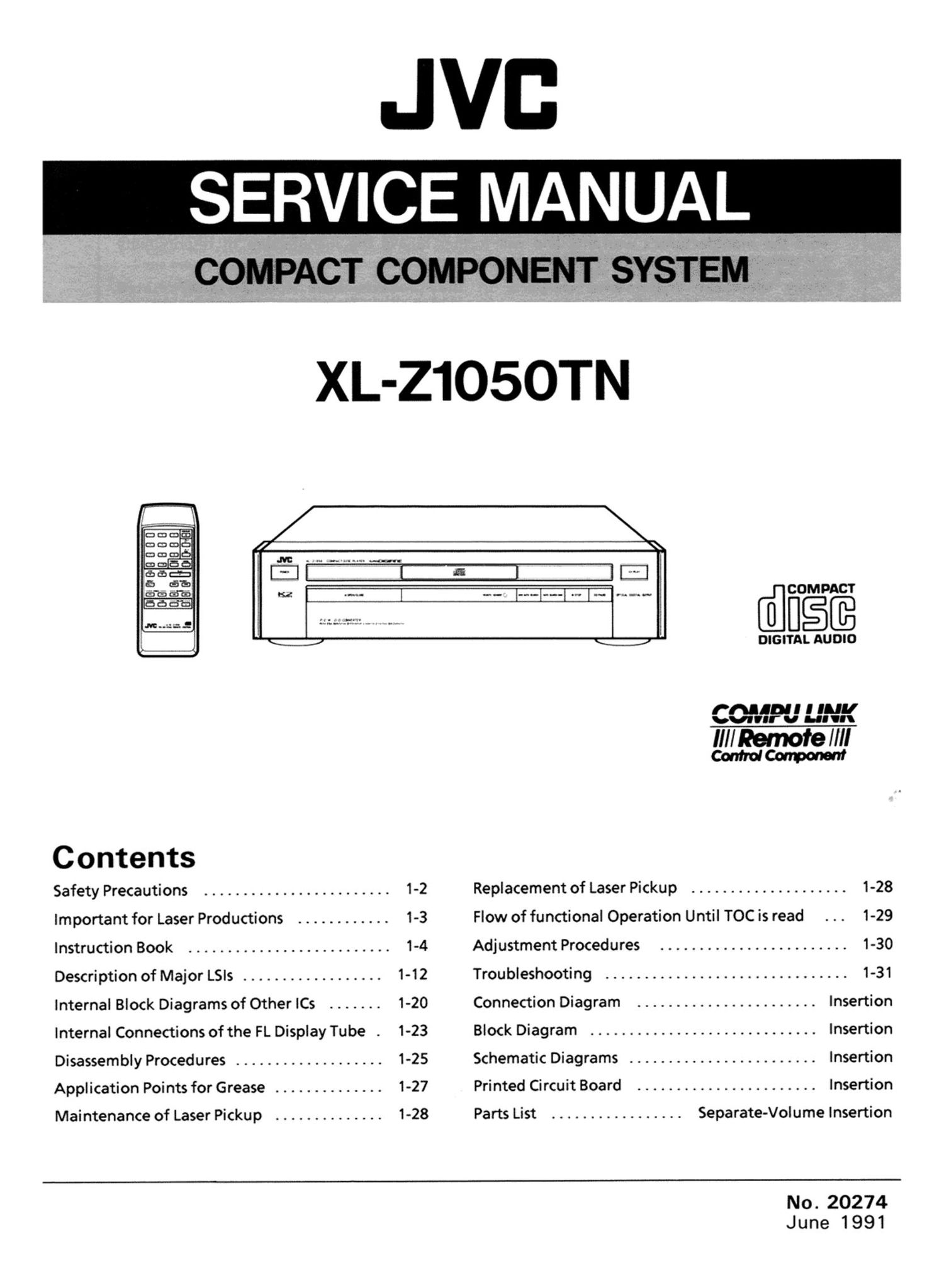
Jvc XLZ 1050 TN Owners Manual

This is the 40 pages manual for Jvc XLZ 1050 TN Owners Manual.
Read or download the pdf for free. If you want to contribute, please mail your pdfs to info@audioservicemanuals.com.

Page: 1 / 40
left right
Jvc XLZ 1050 TN Owners Manual

Extracted text from Jvc XLZ 1050 TN Owners Manual (Ocr-read)


Page 1

@[lfiéfi

DIGITAL AUDIO
CGJPU UHK
Ill/Remote //II
Control Carports!!!
C ontents
Safety Precautions ........................ 1-2 Replacement of Laser Pickup .................... 1-28
Important for Laser Productions ............ 1-3 Flow of functional Operation Until TOC is read . . . 1-29
Instruction Book .......................... 1-4 Adjustment Procedures ........................ 1-30
Description of Major LSls .................. 1-12 Troubleshooting ............................... 1-31
Internal Block Diagrams of Other le ....... 1-20 Connection Diagram ........... . ........... Insertion
Internal Connections of the FL Display Tube . 1-23 Block Diagram ............................. Insertion
Disassembly Procedures ................... 1-25 Schematic Diagrams ........................ Insertion
Application Points for Grease .............. 1-27 Printed Circuit Board ....................... Insertion
Maintenance of Laser Pickup .............. 1-28 Parts List ................. Separate-Volume Insertion
No.20274

June 1991

Page 2

- Safety Precautions

1. The design of this product contains special hardware and many circuits and components
specially for safety purposes. For continued protection, no changes should be made to the
original design unless authorized in writing by the manufacturer. Replacement parts must
be identical to those used in the original circuits. Services should be performed by
qualified personnel only.

2. Alterations of the design or circuitry of the product should not be made. Any design
alterations of the product should not be made. Any design alterations or additions will
void the manufacturer's warranty and will further relieve the manufacture of responsibility
for personal injury or property damage resulting therefrom.

3. Many electrical and mechanical parts in the products have special safety-related
characteristics. These characteristics are often not evident from visual inspection nor can
the protection afforded by them necessarily be obtained by using replacement components
rated for higher voltage, wattage, etc. Replacement parts which have these special safety
characteristics are identified in the Parts List of Service Manual. Electrical components
having such features are identified by shading on the schematics and by (A) on the Parts
List in the Service Manual. The use of a substitute repalcement which does not have the
same safety characteristics as the recommended replacement parts shown in the Parts List of
Service Manual may create shock, fire, or other hazards.

4. The leads in the products are routed and dressed with ties, clamps, tubings, barriers and
the like to be separated from live parts, high temperature parts, moving parts and/or sharp
edges for the prevention of electric shock and fire hazard. When service is required, the
original lead routing and dress should be observed, and it should be confirmed that they
have been returned to normal, after re-assembling.

5. Leakage currnet check (Electrical shock hazard testing)
After re-assembling the product, always perform an isolation check on the exposed metal
parts of the product (antenna terminals, knobs, metal cabinet, screw heads, headphone jack,
contorl shafts, etc.) to be sure the product is safe to operate without danger of electrical
shock.
Do not use a line isolation transformer during this check.

0 Plug the AC line cord directly into the AC outlet. Using a "Leakage Current Tester,
measure the leakage current from each exposed metal parts of the cabinet, particularly
any exposed metal part having a return path to the chassis, to a known good earth
ground. Any leakage current must not exceed 0.5mA AC (r.m.s.).

0 Alternate check method
Plug the AC line cord directly into the AC outlet. Use an AC voltmeter having, 1,000
ohms per volt or more sensitivity in the following manner. Connect a 1,5000 10 W
resistor paralleled by a 0.15 uF AC-type capacitor between an exposed metal part and a

known good earth ground. AC VOLTMETER
Measure the AC voltage across the resistor /7k (Having 1000
ohms/volts,

with the AC voltmeter.

Move the resistor connection to each exposed
metal part, particularly any exposed metal part
having a return path to the chassis, and
meausre the AC voltage across the resistor.

_° Or more sensitivity.)


.15 ,aF AC TYPE

. Pl th
Now, reverse the plug In the AC outlet and prick; 0:
repeat each measurement. Any voltage each exposed
measured must not exceed 0.75VAC (r.m.s.). 1500910W 3' Pa.
This corresponds to 0.5 mA AC (r.m.s.). Good earth ground
~- Warning

1. This equipment has been designed and manufactured to meet international safety standards.

2. It is the legal responsibility of the repairer to ensure that these safety standards are
maintained.

3. Repairs must be made in accordance with the relevant safety standards.
4. It is essential that safety critical components are replaced by approved parts.
5. If mains voltage selector is provided, check setting for local voltage.

1-2 (No.20274)

Page 10

Preliminary Operation

1. Turn on and adjust components such as
an amplifier.

2. Turn on the CD player.

3. Press the [OPENlCLOSE( e )1 button to
slide the disc platter out.

4. With its label side up, put a disc on the
disc platter.

5. Press the [OPENICLOSE ( A )] button
again to slide the disc platter in.

Notes:

0 The display shows the number of tracks
and total playing time of the disc for 3
seconds.

0 You can also close the disc platter by
pressing the [PLAY( p )1 button. In such
a case, play starts immediately with the
first selection at the disc.

To Play From the First Selection
Press the [PLAY( b )1 button.

To Play From Any Desired Selection

Designate the desired selection number by
the 10 key operating buttons.

Examples:

0 To assign the 25th track, press the [+ 10]
button twice and then press the [5] button.

0 To assign the 30th track, press the [ + 10]
button twice and then press the [10]
button.

To Stop Play Temporarily
Press the [PAUSE( ll )] button.

Note:
0 To continue playing, press the [PLAY
( D )1 button.

To Switch Selections During Play

0 To skip to the next selection
Press the [AUTO SEARCH ( DH )] button.

0 To skip to the previous selection

1. Press the [AUTO SEARCH (H1 )] button
once and locate the start of the current
selection.

2. immediately after step 1. press the [AUTO
SEARCH (I44 )1 button again.

To Repeat Play

To repeat all the selections

Press the [REPEAT] button once.

Press the [PLAY ( p )] button.

To repeat one selection

Press the [REPEAT] button twice.
Designate the desired selection number
by the [AUTO SEARCH (Dbl )] buttons.
Press the [PLAY( b )] button.

9 NHeNro

To Stop Play
Press the [STOP/CLEAR ( I )] button.

To Remove the Disc
Press the [OPENICLOSE ( e )1 button.

1-10 (No.20274)

HOW TO OPERATE

To Program Play

1. Press the [STOP/CLEAR ( I )1 button.

2. Press the [PROGRAM] button.

3. Program any desired selections with the
10 key operating buttons.

4. Press the [PLAY ( b )] button.

Notes:

0 Up to 32 selections can be programmed.

0 When programming is canted out with the
disc platter out, the total playing time at
the programmed selections will not be
displayed.

0 When the total playing time of all the
selected tunes exceeds 99 minutes and
59 seconds, the time display will be disa-
bled and only the center bars will be dis-
played.

To Correct the Program

0 To correct all the program

1. Press the [STOP/CLEAR( I )] button.

2. Start programming again from the be-
ginning.

. To correct each content ol the program

1. Press the [AUTO SEARCH ( 144)] button
to go back to the program which needs to
be canceled.

2. Press the [PRGM CANCEL] button.

3. Program a desired selection with the 10
key operating buttons.
' Newly programmed selection is added

to the last of the program.

To Check the Program

Press the [AUTO SEARCH ([44 , ppm]
button.

To cancel program play mode. press the
[PROGRAM] button so that the PRGM" in-
dicator goes out.

To Perionn Synchronized Recording

Synchronized recording is possible by con-

necting the cassette deck to the COMPU

LINK-1ISYNCHRO terminals of the CD play-

er through the remote cable.

1. Press the [REC (0)] and [PAUSE ( ll )]
buttons of the cassette deck.

2. Press the [PLAY ( > )1 button of the CD
player to start the synchronized recording.

To Perform Edit Recording

0 Auto Edit Recording

1. Set a disc and press the [STOP/CLEAR
( I 1] button.

2. Press the [EDITING MODE] button once
so that EDIT, AUTO" is displayed.

3. Using the 10 key operating buttons, desig-
nate the time interval according to the
tape length. If the tape length is equal to
the indication in the display, press the
[SIDE AIB] button.

4. Place the cassette deck in REC PAUSE

mode.
This operation is limited to the units us-
ing JVCs COMPU LINK system. For other
cassette deck, set the deck in recording
status.

_11_

5. Press the [PLAY( b )1 button.
When the last selection programmed on
the A side of the tape ends, the edit
recording automatically stops. To record
in the other side of the tape. repeat the
steps 4 and 5 after turning over the tape.

0 Program Edit Recording

Set a disc and press the [STOPICLEAR

( I )] button.

Press the [EDITING MODE] button twice

so that EDIT. PRGM" is displayed.

Using the 10 key operating buttons, desig-

nate the time interval according to the

tape length. If the tape length is equal to

the indication in the display, press the

[SIDE AIB] button.

Program any desired selections with the

10 key operating buttons.

After you finish the programming of A side

of the tape press the [SIDE A/B] button.

Repeat the step 4 and 5.

Place the cassette deck in REC PAUSE

mode.

This operation is limited to the units us-

ing JVC's COMPU LINK system. For other

cassette deck, set the deck in recording

status.

8. Press the [PLAY ( b )] button to start
recording.
When the last selection programmed on
the A side of the tape ends. edit record-
ing automatically stops. To record in the
other side of the tape, repeat the steps 7
and 8 after turning over the tape.

9.?

399?

Notes:

0 When the programming is in excess of the
designated time interval, the excess time
blinks in the display. In such a case. press
the [PRGM CANCEL] button to cancel the
last programmed selection.

0 During the programming, the selections
which cannot be recorded in the designat-
ed time intervais blink in the program
chart.

0 To cancel the editing status, press the
[STOPICLEAR ( I )1 button twice.

To start playback using an audio

timer

If you connect a timer component to the CD

player you can preset the time for play to

start. For example if you want to wake up to

music.

1. Place a disc on the tray and then switch
off the power.

2. Connect the CD players power cord to the
timer.

3. Switch the [TIMER PLAY] switch on.

4. Piess on the power button on the CD
player.
At the preset time play will start with the
first track on the CD.

Page 37

MEMO -

(No.20274) 1-37