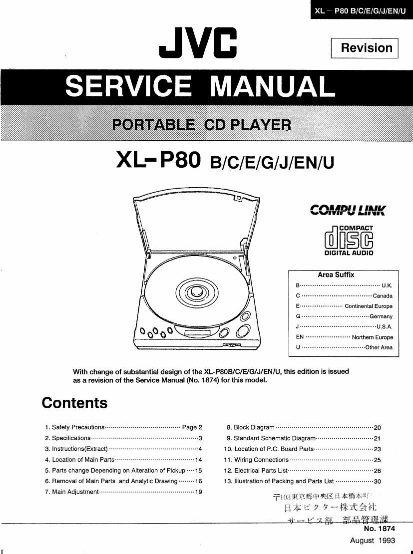
Jvc XLP 80 B Service Manual

This is the 47 pages manual for Jvc XLP 80 B Service Manual.
Read or download the pdf for free. If you want to contribute, please mail your pdfs to info@audioservicemanuals.com.

Page: 1 / 47
left right
Jvc XLP 80 B Service Manual

Extracted text from Jvc XLP 80 B Service Manual (Ocr-read)


Page 1

XL 7 P80 B/C/E/G/J/EN/U

Jvc


CO... I I ll"!
Vlnr v I." l

@CIEEE

DIGITAL AUDlD

Area Suffix


......... U.K.

----- Canada

Continental Europe


................. Germany
................ U.S.A.

Northern Europe
U .................................. Other Area

With change of substantial design of the XL-PSOB/ C/E/G/J/ EN IU, this edition is issued
as a revision of the Service Manual (No. 1874) for this model.

Contents

1. Safety Precautions ------------ 8. Block Diagram ------------------------

2. Specifications ~~~~~~~~~~~~~~~~~~~ 9. Standard Schematic Diagram---~

3. Instructions(Extract) ---------- 10. Location of PC. Board Parts -----

4. Location of Main Parts ------- ---14 11. Wiring Connections

5. Parts change Depending on Alteration of Pickup ----15 12. Electrical Parts List ---------------

6. Removal of Main Parts and Analytic Drawing -------- 16 13. Illustration of Packing and Parts List ----------------- 30
7. Main Adjustment ------------------------------------------------ 19

ans hi1 Tfiiéria 19-15:: B mm?
H4L7¢MMKA*

+i' w- I 71 {fl Ei'i rthlIgflfii'gt
NO. 1874

August 1993

Page 2

XL W P80 B/C/E/G/J/E

1. Safety Precautions

IMPORTANT FOR LASER PRODUCTS

XL - P80 C/J
C It 0

PRECAUTIONS
1. CLASSl LASER PRODUCT
2. DANGER: Invisible laser radiation when open and

interlock failed or defeated. Avoid direct exposure to

been I:
3. CAUTION: Do not open the bottom cover. There are 0 )

no user serviceable parts inside the unit; leave all
servicing to qualified service personnel.

4 CAUTION: Use of controls or adjustments or
performance or procedures other than those specified Product complies with DHHS Rules 21 US JVC CORP.
herein may result in hazardous radiation exposure. CFR Subchapter J in effect at date of 41 SLATER DRIVE

manufacture. ELMWOOD FARK

NJ. 07407
MANUFACTURED MANUFACTURED

_ AT 2-
MADE IN JAPAN

Notes:
'1 The date of manufacture.
'2 The ID code of manufacturing plant.

XL - P80 B/E/G/Gl/EN

cuss 1
l: LASER PRODUCT

Obx:

O O Apparaten lnnehSller laser-
kernponent Iv hfigre laserklass
5n kiss 1.

ADVARSEL-Der vrl udslralcs DANGEvanvismle laser
osynlig laserheslrallng nar radiation when open and
apparalet abnes og altos» inlerleck deleated
ningsmekanismen frigorcs AVOID DlRECT EX-
UNDGA AT BLlVE UDSET POSURE T0 BEAM
FOR LASERBESTRAUNG

1).. lhhtnlfw "uh wllh mowm-a wmr.

CAUTION wrmm m mint-:4 vlnwln, i. armed to

n m um um to r . mum of unlmimd

30%;;qu "dlnwreul velar" wlmln an new.

Inflow rim my in of lulllelam nuw.

war to mnulruu - rm efulncvle mm in

WHO. 70 IIDUCI 4 1! OF ILlcYMC IHOCK. DIflDflll
DO NOT REMOVI COVER [0! IACKL

N0 UlllvElVlClAlLl M1INNDI. Thl Didn't-Iliad polnl wllNlI In will!!!

nun :uwicmn to auAuma tlflvchPtRiDNNEL. new: i: lntvridad te Illfl m um lu rm

prmnu o! lmponlnt owning and min.

Mm (uniting) Inulucliem in nu litera-
qu aerampmylng the Invlhm.

2 (Nor 1874)

Page 12

XL ~ P80 B/C/E/G/J/EN/U

' Use the remote cable (3.5 mm dia. mini plug) available from an audio store or JVC parts number "EWPBO5-001E" lor COMPU
LINK connections. For more details. consult your nearest JVC dealer.

Notes:

I Be sure to use the Ac adapter when connecting a
remote cable to the COMPU LINK-1 jack.

0 Set the power oi the XL-Pao on when connecting a
remote cable to the COMPU LINK-i jack.

0 When connecting a remote cable to the COMPU LINK-1
Jack. the provided connection cord must be also
connected.

I The Ante Power Off function does not work when the
COMPU LINK-1 jack is connected.

0 To avoid misoperatlon. do not set the CD player to the
pause mode at the beginning oi synchronized recording.

0 During synchronized recording. the CD player will not
enter the pause mode.

0 The data stored in the CD player (or programmed play will
be cancelled when the FUNCTION switch of the amplifier
is switched over.

0 CD auto search is possible using the remote control unit
provided with the amplifier.

3. Connection to car audio system

Power Is supplied from the car adapter: use a cassette
adapter or noise filter cord to connect the signal card.

I For these connections. refer to the Instruction book of
each accessory.

To AUX terminal (3.5 mm dia. stereo mini plug)

\
Cigarette lighter socket Noise filter cord (KS-U32) (optional)

R

Car adapter (CA-R451) (optional) %

\

Car audio cassette adapter
(CA-R61) (provided)

Flexible mounting arm (CA-RM) (optional)

12 (No. 1874)