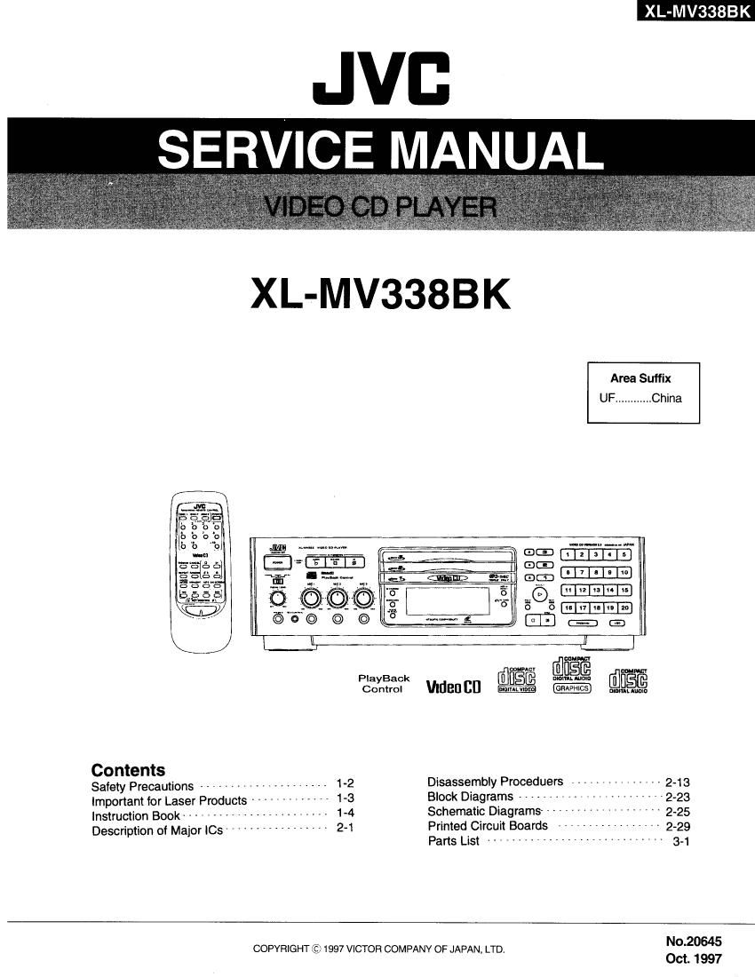
Jvc XLMV 338 BK Service Manual

This is the 82 pages manual for Jvc XLMV 338 BK Service Manual.
Read or download the pdf for free. If you want to contribute, please mail your pdfs to info@audioservicemanuals.com.

Page: 1 / 82
left right
Jvc XLMV 338 BK Service Manual

Extracted text from Jvc XLMV 338 BK Service Manual (Ocr-read)


Page 2

,XL-MvsgBK

-Safety Precautions

1.This design of this product contains special hardware and many circuits and components specially
for safety purposes. For continued protection, no changes should be made to the original design
unless authorized in writing by the manufacturer. Replacement parts must be identical to those
used in the original circuits. Services should be performed by qualified personnel only.

2. Alterations of the design or circuitry of the product should not be made. Any design alterations of
the product should not be made. Any design alterations or additions will void the manufacturers
warranty and will further relieve the manufacture of responsibility for personal injury or property
damage resulting therefrom,

3. Many electrical and mechanical parts in the products have special safety-related characteristics.
These characteristics are often not evident from visual inspection nor can the protection afforded
by them necessarily be obtained by using replacement components rated for higher voltage,
wattage, etc. Replacement parts which have these special safety characteristics are identified in
the Parts List of Service Manual. Electrical components having such features are identified by
shading on the schematics and by (A) on the Parts List in the Service Manual. The use of a
substitute replacement which does not have the same safety characteristics as the recommended
replacement parts shown in the Parts List of Service Manual may create shock, fire, or other
hazards.

4. The leads in the products are routed and dressed with ties, clamps, tubings, barriers and the
like to be separated from live parts, high temperature parts, moving parts and/or sharp edges
for the prevention of electric shock and fire hazard. When service is required, the original lead
routing and dress should be observed, and it should be confirmed that they have been returned
to normal, after re~assembling.

5.Leakage currnet check (Electrical shock hazard testing)

Alter re-assembling the product, always perform an isolation check on the exposed metal parts

of the product (antenna terminals, knobs, metal cabinet. screw heads, headphone jack, control

shafts, etc.) to be sure the product is safe to operate without danger of electrical shock.

Do not use a line isolation transformer during this check.

0 Plug the AC line cord directly into the AC outlet. Using a "Leakage Current Tester", measure
the leakage current from each exposed metal parts of the cabinet, particularly any exposed
metal part having areturn path to the chassis, to a known good earth ground. Any leakage
current must not exceed 0.5mA AC (r.m.s.)

0 Alternate check method
Plug the AC line cord directly into the AC outlet. Use an AC voltmeter having, 1,000 ohms
per volt or more sensitivity in the following manner. Connect a 1,5009 10W resistor paralleled by
a 0.15uF AC-type capacitor between an exposed

metal part and a known good earth ground. fixggigggm
Measure the AC voltage across the resistor with the ohms/volts,

AC voltmeter. or more sensitivity)
Move the resistor connection to eachexposed metal

part, particularly any exposed metal part having a 0.15): AC TYPE

return path to the chassis, and meausre the AC ,
voltage across the resistor. Now, reverse the plug in -"_- 33E: 3:3
the AC outlet and repeat each measurement. voltage ' Wl, " > each exposed
measured Any must not exceed 0.75 V AC (r.m.s.). 15009 10W metal part

This corresponds to 0.5 mA AC (r.m.s.).
Good earth ground

- Warning

1.This equipment has been designed and manufactured to meet international safety standards.

2. It is the legal responsibility of the repairer to ensure that these safety standards are maintained.
3. Repairs must be made in accordance with the relevant safety standards.

4. It is essential that safety critical components are replaced by approved parts.

5.lf mains voltage selector is provided, check setting for local voltage.

1-2

Page 13

Description of Major 10s
I MD6433726$D43F(IC201) : SYSTEM MICON

XL-MV338BK

1.Pin Layout KEY matrix
54 ~ 41 IN KEYIN5 KEYINA KEYIN3 KEYINZ KEY|N1
OUT (25PIN) (26PlN) (27PlN) (28PIN) (21PIN)
40 SG/KEYOO Z 3 4 5
2 (41pm) ($921) ($922) ($923) (5924) ($925)
25 7G/KEYO1 7 8 9 10
1 N 24 (42pm) (S926) (S927) (S928) (5929) ($930)
6G/KEYO 2 12 13 14 15
(43P1N) (S931) (5932) ($933) (5934) (5935)
KEY iNPUT SG/KEY03 17 18 19 20
PIN NO. INPUT (44mm (5936) (5937) (5933) (S939) (S940)
P.SW POWER ZlG/KEYO 4 I .. PROGRAM 4- 20
(53mm (5951) (45PIN) (5920) (5919) (5941) (5940)
FM sw FM ON 3G/KEYO 5 MPX l« DISC1= DISC 1
(S3PlN) ($952) (ASPIN) (S903) (5918) (5908) (5911)
55915: $352? ZG/KEYO s RETURN Mgm'l-G »l mm a DISC 2
KEY NOR KEY NOR 7) (S905) (5902) (5917) (5907) (5910)
(SOPIN) (S957) VOICE
INTR I > DI 3: DI
KEY DN KEY DOWN (it/123187 (S901: CHANGE (5916) (55:06) (5:593)
(51PIN) ($958) ($901)
2. Description
'2': symbol IIO Description lfl: symbol I/O Description
1 W I Tracking lock signal input 50 KEY NOR I KEY NOR key input
2 TocT< I Focus lock signal input 51 KEY DN I KEY DN key Input
3 SENSE I Sense signal Input 52 W I POWER key input
4 TVSW | PALL NTSC select terminal 53 FM.SW I FM key input
5 AVSS ~- (Pull up) 54 NC -~ Not use
6 TEST -- (Pull down) 55 FM.P.0N 0 FM POWER control output
7 x2 -- Not use 56 W o FMMUTE control output
8 X1 I (Pull up) 57 +5V -- Power suplly(+5V)
9 GND ~~ GND 58 m 0 Power ON/OFF control output
10 OSCI -- Xtal osillator connection 59 Wr- 0 Reset signal output
11 OSCZ -- X'tal osillator connection 60 IFL lC301
12 W | Reset signal input 61 IFS lC301
13 HREQ | Communication signal input 62 IFD 0 Data for IC301
14 WW | Remote signal input 63 OSDDT 0 Command data signal output forlC106
15 C3DT 0 Command data signal output 64 OSDCLK 0 Command clock signal output forlC106
16 C3CLK 0 Command clock signal output forlC 65 OSDCS 0 Chip select forlClOS
17 C3REQ l Command request signal 66 MREQ 0 Data trancefer request signal output
18 C3CS 0 Chip select forlc 67 SQCK 0 Outside clock terminal for Subcode Q
reSIstor
19 NC ~~ Not use 68 SUBQ I Subcode Q code input
20 CS l Chip select terminal (Pullup) 69 VCDRST 0 Reset signal output
21 D3,IND O DICK3 indication ONIOFF signal output 70 SRCLX O
22 D2.IND O DICKZ indication ON/OFF signal output 71,72 MZHDT/HZMD l/O Serial data output
23 HRDY | Communication signal input 73 MLD 0 Command load signal output
24 D1,IND 0 DICK1 indication ON/OFF signal output 74 MDATA 0 Command data signal output
25~29 KEYIN1~5 I Key matrix input 75 MCLK 0 Command clock signal output
30 NC -- Not use 76 + 5V -- Power suplly(+ 5V)
31~39 S1~59 0 FL segment control output 77 MODESW l MODE select terminal
40 -VDISP -- FL- Power suplly 78 ECHOVOL l ECHOVOL control input
41~48 sogggo; o :btga'td °°""°' 9 Key at 79 REST I Reset signal input
49 KEY UP l KEY UP key input 80 STAT l Status signal (IC603)input

2-1

Page 15

XL-MV33SBK

3. Functions
Pi" N°~ Symbol IIO Functionsand operations

1 PD I APC amp input terminal
2 LD 0 APC amp output terminal
3 LD ON I AFC ON/OFF control terminal
4 LDP -- Connected to ground
5 VCC ~- Power supply
6 RF- l Inverse input pin for RF amp
7 RF OUT 0 RF amp output
8 RFIN I RF input
9 CAGC IIO Connecting pin of AGC loop filter
10 ARE 0 RF output
11 C.ENV 1/0 A capacitor is connected to this terminal to detect the envelope of RF signal
12 CEA 1/0 A capacitor is connected to this terminal to detect the envelope of RF signal
13 CS BDO I/O A capacitor is connected to detect the lower envelope of the RF signal
14 500 o BDO output pin
15 CS BRT IIO A capacitor is connected to detect the lower envelope of the RF signal
16 OFTR O Of-track status signal output
17 /NRFDET 0 RF detection signal output
18 GND -- Ground
19 ENV 0 Envelope output
20 VREF 0 Reference voltage output
21 LB OFF -- Connect to ground
22 VDET O Vibration detection signal output
23 TE BPF I Input pin of tracking error through BPF
24 CROSS 0 Tracking error cross output
25 TE OUT 0 Tracking error signal output
26 TE- l Inverse input pin for tracking error amp
27 FE OUT 0 Output pin of focus error
28 FE- I Inverse input pin for focus error amp
29 FBAL I Focus balance control
30 TBAL I Tracking balance control
31 PDFR l/O F lvV amp gain control
32 PDER l/O E W amp gain control
33 PDF l I-V amp input
34 PDE | |~V amp input
35 PD BB | I-V amp input
36 PD AC | |»V amp input

2-3