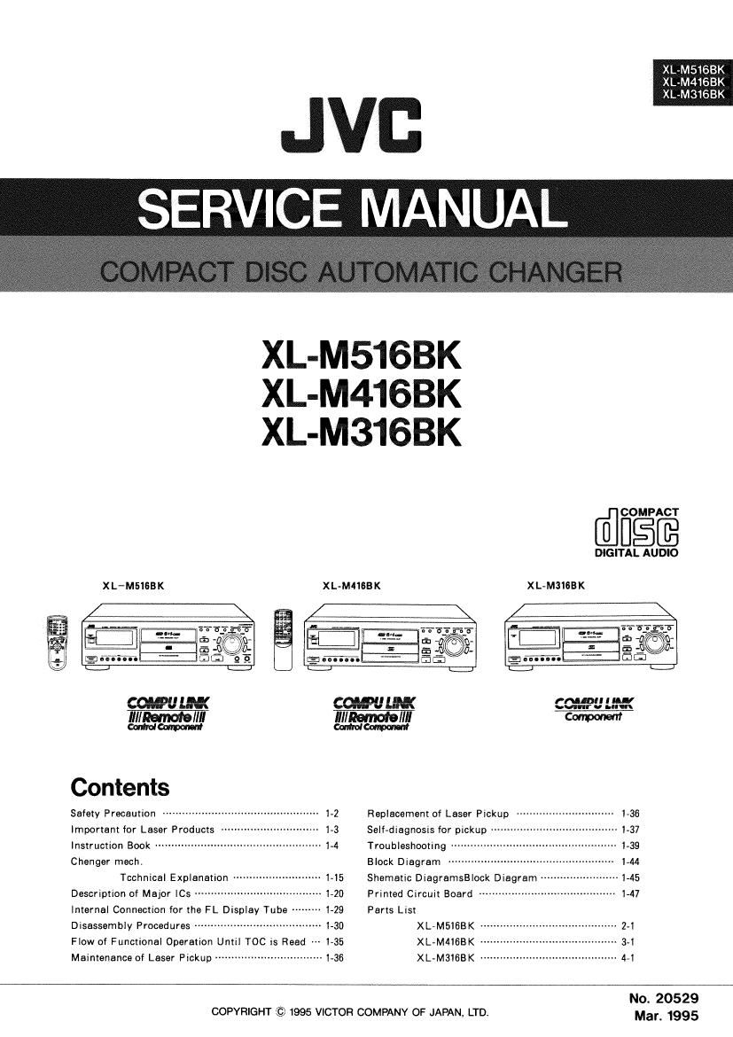
Jvc XLM 516 BK Service Manual

This is the 102 pages manual for Jvc XLM 516 BK Service Manual.
Read or download the pdf for free. If you want to contribute, please mail your pdfs to info@audioservicemanuals.com.

Page: 1 / 102
left right
Jvc XLM 516 BK Service Manual

Extracted text from Jvc XLM 516 BK Service Manual (Ocr-read)


Page 2

XL-M51SBK
XL-M416BK
XL-M3168K

1

- Safety Precautions

.The design of this product contains special hardware and many circuits and components
specially for safety purposes. For continued protection, no changes should be made to the
original design unless authorized in writing by the manufacturer. Replacement parts must
be identical to those used in the original circuits. Services should be performed by
qualified personnel only.

.Alterations of the design or circuitry of the product should not be made. Any design
alterations of the product should not be made. Any design alterations or additions will
void the manufacturer's warranty and will further relieve the manufacture of responsibility
for personal injury or property damage resulting therefrom.

. Many electrical and mechanical parts in the products have special safety-related
characteristics. These characteristics are often not evident from visual inspection nor can
the protection afforded by them necessarily be obtained by using replacement components
rated for higher voltage, wattage, etc. Replacement parts which have these special safety
characteristics are identified in the Parts List of Service Manual. Electrical components
having such features are identified by shading on the schematics and by (A) on the Parts
List in the Service Manual. The use of a substitute repalcement which does not have the
same safety characteristics as the recommended replacement parts shown in the Parts List of
Service Manual may create shock, fire, or other hazards.

.The leads in the products are routed and dressed with ties, clamps, tubings, barriers and
the like to be separated from live parts, high temperature parts, moving parts and/or sharp
edges for the prevention of electric shock and fire hazard. When service is required, the
original lead routing and dress should be observed, and it should be confirmed that they
have been returned to normal, after re-assembling.

. Leakage currnet check (Electrical shock hazard testing)

After re-assembling the product, always perform an isolation check on the exposed metal
parts of the product (antenna terminals, knobs, metal cabinet, screw heads, headphone jack,
contorl shafts, etc.) to be sure the product is safe to operate without danger of electrical
shock.

Do not use a line isolation transformer during this check.

0 Plug the AC line cord directly into the AC outlet. Using a "Leakage Current Tester,
measure the leakage current from each exposed metal parts of the cabinet, particularly
any exposed metal part having a return path to the chassis, to a known good earth
ground. Any leakage current must not exceed 0.5mA AC (r.m.s.).

0 Alternate check method
Plug the AC line cord directly into the AC outlet. Use an AC voltmeter having, 1,000
ohms per volt or more sensitivity in the following manner. Connect a 1,5009 10 W
resistor paralleled by a 0.15 pF AC-type capacitor between an exposed metal part and a
known good earth ground.
Measure the AC voltage across the resistor
with the AC voltmeter.
Move the resistor connection to each exposed
metal part, particularly any exposed metal part
having a return path to the chassis, and
meausre the AC voltage across the resistor.
Now, reverse the plug in the AC outlet and
repeat each measurement. Any voltage
measured must not exceed 0.75VAC (r.m.s.).
This corresponds to 0.5 mA AC (r.m.s.).

1.
2.

3.
4.
5.

- Warning

This equipment has been designed and manufactured to meet international safety standards.

It is the legal responsibility of the repairer to ensure that these safety standards are
maintained.

Repairs must be made in accordance with the relevant safety standards.
It is essential that safety critical components are replaced by approved parts.
If mains voltage selector is provided, check setting for local voltage.

1-2

Page 26

XL-MSISBK
XL-M4163K
XL-M31GBK

I MN35503(|C750) : D /ACONVERTER

1. Terminal Layout 2. Block Diagram

MA 1 28 PM ,_ _____________ .1
DIN 2 27 MD l DF BLOCK l
LRCK 3 26 MC Dm l - I 3 XIN
BCK 4 25 M3 . I I osc
MB 5 24 DVDDI LRCK I stOVER r BLOCK 2 XOUT
DVDDZ 6 23 XI BLOCK : SAMPLING I
CKO 7 22 XOUT BCK ' DIG TER l.__:
DVSSS 8 21 DVSS1 : ITAL FlL I
M1 9 20 M2 M1 ' I : 6541 P00
ounc 10 19 ourzc I :
NC 11 18 NC M2 MODE : ¢ I
AVDD1D 12 17 AVDDI CONTROL : :
OUT") 3 6 ourzo M3 - BLOCK : ISTORDERNOISE : ->E]cn AVSS 4 5 "552 : SHAPER BLOCK :
MA n. ________________ J
r-""'-"""""I
I I
MB : I
I VANS I
MD : BLOCK :
I I
MC ...... J l
I
ounc IE PEM FEM : 1 outzc
ounn IE1 BLOCK BLOCK : I cum)
1
WA BLOCK j
3.Description
Pin . a Pin . .
No Symbol IIO DescriptIon No Symbol I/O DescriptIon
1 DIN I Operational node 4 15 AVSSZ - Analog ground 2
2 DIN I DATA input 16 OUTZd 0 2D FEM output
3 LRCK I LR clock input 17 OU'I'ZD 0 2D PEM output
4 BCK l Bit clock input 18 NC - Non comedian
5 MB I Operational mode control 5 19 OUTZC 0 2C FEM output
6 DVDDZ -- Digital power supply 2 20 M2 0 Operational node 2
7 CKO o Clock output 21 DVSSI - Digital ground._pin 1
8 DVSSZ ~ Digital ground 2 22 XOUT 0 Crystal oscillator output
9 M1 -- Connected to ground 23 XIN I Crystal oscillator input
10 OUT1C 0 1C PEM output 24 DVDDJ - Digitalpower supply 1
11 NC 0 Non conection 25 M3 l Operationalnode 3
12 AVDD1 - Analog power supply 1 26 MC l Resatsignall DigitaLAtL control signal input
13 OUTID 0 1D FEM output 27 MD | Resetsignal/Digital Att. control signal input
14 AVSS1 -- Analog ground 1 28 PDO 0 Phase comparatoroutput pin

1-26

Page 91

wmbolfla; WELT/LE

XE-MSWB K

[PARTS LIST
A Item Part Number Part Name Q'ty Description Area
1 EFP-XLM31GBKE(S FRONT PANEL ASS'Y 1 BS,EF,EN,G
EFP-XLM31GBKU(S FRONT PANEL ASS'Y 1 U
1-1 E103004-0135M FRONT PANEL 1 BS,EF,EN,G
1-1 E103004»017SM FRONT PANEL 1 U
1-2 E309341~0095M WINDOW SCREEN 1
1-3 VJD5429-001 JVC MARK 1
2 E309345-0045M CD FITTING 1
3 E309339-0025M KNOB 1
4 E408778-0025M SHEET ASSY 1
5 95896-001 SPACER 2 FRONT FOOT U
6 E208468-0025M PUSHBUTTON 1 PLAY/PAUSE
7 E208466~0025M PUSH BUTTON 1 POWER
8 E309343-0025M LID PLATE 1
9 93534-001 SPRING 1
1O SDSGSOOGM TAPPING SCREW 3 BS.EF;EN,G
SDSG3006M TAPPING SCREW 5 U
11 SDSFZGOSZ SCREW 13
12 810746900155 WIRE CLAMP 1
13 E72405-001 SPECIAL SCREW 2
14 FSYH40013001= FOOT 4 BS,EF,EN,G
VJ F4039-00H FOOT 2 U
15 SBST30082 TAPPING SCREW 4 FOR FOOT BS,EF.EN,G
SBST30082 TAPPING SCREW 2 FOR FOOT U
16 806805-134 SPACER 1 CHASSIS BASE
17 E408823-001SM SUPPORT BRACKET 1
13 809520-001 LEAF SPRING 1
19 E103006-001SM CHASSIS BASE 1
20 535630082 TAPPING SCREW 4
21 SBSFBOOBZ TAPPING SCREW 2
22 VWF1234-16TTB FFC CABLE 1
23 ~~~~~~~ CD-CH MECHA 1 SEE PAGE
24 mm... CD MECHA 1 SEE PAGE 4-6
25 E308181AZZISS FFC HOLDER 1
26 606805-163 SPACER 1 CD MECH P.C.B
27 E407153-001 INSULATOR 4
28 E408361-001 SCREW 4
29 E408373-001 SPRING(BLACK) 2
30 E408373-002 SPRING 2
31 VWF1015~16PPA FFC CABLE 1
32 GBSGSOOBCC TAPPING SCREW 4
A 33 ETP1000«86EAI POWER TRANSFORMER 1 EF,EN,G
A ETP1000-86EAIBS POWER TRANSFORMER 1 BS
[A ETP100mW POWER TRANSFORMER 1 U
34 E65389-004 SPECIAL SCREW 2 ' POWER TRANSFORMER
35 E208470-007SM REAR PANEL 1 BS,EF.EN,G
35 E208470-OOBSM REAR PANEL 1 U
36 E73273-006 SPECIAL SCREW 8
37 E206967~005 METAL COVER 1
38 EW1 SPECIAL SCREW 4
39 53058954 61 SPACER 1 CH MECHA TOP FRONT
40 SBSFZGOSM TAPPING SCREW 2 VOLSEL. U
41 5406507-001 CAUTION LABEL 1
- E70891<001 CLASS1 LABEL 1
» E408450-001 CE LABEL 1 BS,EF.EN,G
- E7002$001 APPROVAL LABEL 1 EN
- E70419-003F FTZ MARK LABEL 1 G
- E75139-003 Z LABEL 1 U
- QZL1007-001 BEAB LABEL 1 BS
- QZL1031-101 LABEL 1 EF
The Marks for Designated Areas
EF .... Continental Europe EN .... Scandinavia BS ..... the U.K G ...... Germany
U ..... Universal Type

No mark indicates all area.

4-3