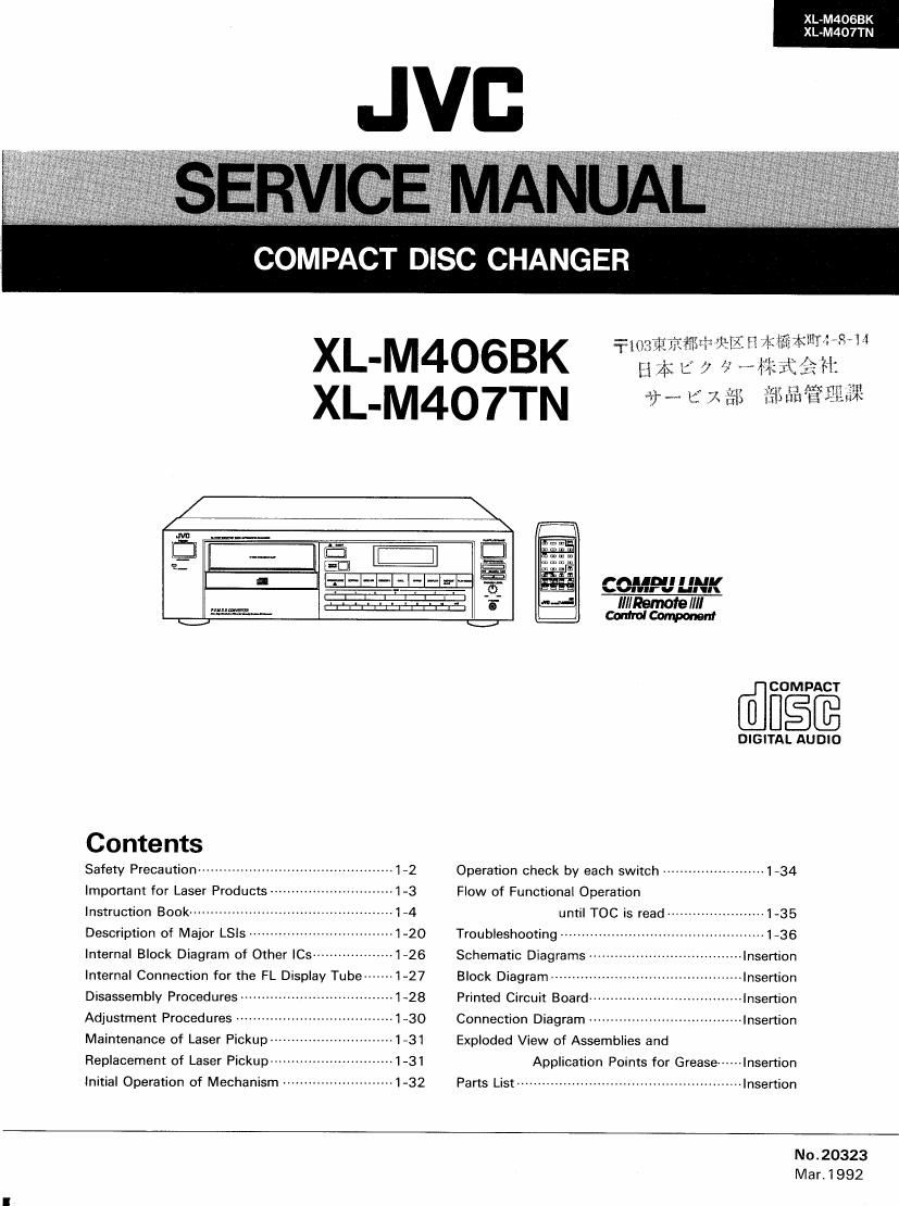
Jvc XLM 406 BK Service Manual

This is the 93 pages manual for Jvc XLM 406 BK Service Manual.
Read or download the pdf for free. If you want to contribute, please mail your pdfs to info@audioservicemanuals.com.

Page: 1 / 93
left right
Jvc XLM 406 BK Service Manual

Extracted text from Jvc XLM 406 BK Service Manual (Ocr-read)


Page 1

XL-M4OSBK
XL-M407TN

COMPACT DISC CHANGER

XL-M4OGBK
XL-M4O7TN fiwlfixafit agitate?

firm ES

ED
" f""" 77. COP-{P'JUNK
WW % Minors/III
K.)
@ filMPACT
DIGITA§J§
Contents
Safety Precaution ------------------------ 12 Operation check by each switch -------------------- 1734
Important for Laser Products~m ~---1~3 Flow of Functional Operation
|nstrucfion Book ............................................... 14 um" TQC is read ....................... 1-35
Description of Major LSls ---------------- 1-20 Troubleshooting ------- ---~«-1~36
Internal Block Diagram of Other |Cs~~ r1726 Schematic Diagrams Insertion
Internal Connection for the FL Display Tube ------ 1-27 Block Diagram ---------- mlnsertion
Disassembly Procedures-a 1~28 Printed Circuit Board --------------------------------- Insertion
Adjustment Procedures 1-30 Connection Diagram -------------------------------- Insertion
Maintenance of Laser Pickup~~ ....1_31 Exploded View of Assemblies and
Replacement of Laser Pickup -------------------------- 1-31 Application Points for Grease ----- Insertion
initial Operation of Mechanism .......................... 1-32 Parts List ..................................................... Insertion
No.20323
Mar. 1 992

Page 2

XL-M4OSB

XL-M407TN

-- Safety Precautions

J

1. The design of this product contains special hardware and many circuits and components

specially for safety purposes. For continued protection, no changes should be made to the
original design unless authorized in writing by the manufacturer. Replacement parts must
be identical to those used in the original circuits. Services should be performed by
qualified personnel only.

.Alterations of the design or circuitry of the product should not be made. Any design

alterations of the product should not be made. Any design alterations or additions will
void the manufacturer's warranty and will further relieve the manufacture of responsibility
for personal injury or property damage resulting therefrom.

.Many electrical and mechanical parts in the products have special safety-related

characteristics. These characteristics are often not evident from visual inspection nor can
the protection afforded by them necessarily be obtained by using replacement components
rated for higher voltage, wattage, etc. Replacement parts which have these special safety
characteristics are identified in the Parts List of Service Manual. Electrical components
having such features are identified by shading on the schematics and by (A) on the Parts
List in the Service Manual. The use of a substitute repalcement which does not have the
same safety characteristics as the recommended replacement parts shown in the Parts List of
Service Manual may create shock, fire, or other hazards.

.The leads in the products are routed and dressed with ties, clamps, tubings, barriers and

the like to be separated from live parts, high temperature parts, moving parts and/or sharp
edges for the prevention of electric shock and fire hazard. When service is required, the
original lead routing and dress should be observed, and it should be confirmed that they
have been returned to normal, after re-assembling.

. Leakage currnet check (Electrical shock hazard testing)

After re-assembling the product, always perform an isolation check on the exposed metal
parts of the product (antenna terminals, knobs, metal cabinet, screw heads, headphone jack,
contorl shafts, etc.) to be sure the product is safe to operate without danger of electrical
shock.

Do not use a line isolation transformer during this check.

0 Plug the AC line cord directly into the AC outlet. Using a "Leakage Current Tester",
measure the leakage current from each exposed metal parts of the cabinet, particularily
any exposed metal part having a return path to the chassis, to a known good earth
ground. Any leakage current must not exceed 0.5mA AC (r.m.s.).

0 Alternate check method
Plug the AC line cord directly into the AC outlet. Use an AC voltmeter having, 1,000
ohms per volt or more sensitivity in the following manner. Connect a 1,5000 10 W
resistor paralleled by a 0.15 ,uF AC-type capacitor between an exposed metal part and a
known good earth ground. Ac VOLTMETER

Measure the AC voltage across the resistor E (Having 1000

with the AC voltmeter. ohms/volts, .. ,
Move the resistor connection to each exposed a 0. ° m°ree""t"ty')
metal part, particularly any exposed metal part

having a return path to the chassis, and 0-15/AF AC TYPE

meausre the AC voltage across the resistor. -"- Place this
Now, reverse the plug in the AC outlet and w_ pmbe on
repeat each measurement. Any voltage 1500010W gagglegggtsed

measured must not exceed 0.75 V AC (r.m.s.).
This corresponds to 0.5 mA AC (r.m.s.). Good earth ground

$>

- Warning

, This equipment has been designed and manufactured to meet international safety standards.
. It is the legal responsibility of the repairer to ensure that these safety standards are

maintained.

. Repairs must be made in accordance with the relevant safety standards.
. It is essential that safety critical components are replaced by approved parts.
. If mains voltage selector is provided, check setting for local voltage.

1*2(No,20323)

Page 9

XL-M4OGBK
XL-M407TN

CONNECTION

9 Do not connect the power plug until all connections are completed
0 Connect the plugs firmly.
o This diagram is given as an example.

I Connecting to the OUTPUT jacks
XL-M4OTTN/XL-M4068K/XL-MSOTTNIXL-MBOGBK
EZZE)


Example:
A receiver which has COMPU
LINK termlnals

.1

Connect the OUTPUT jacks of this unit to the CD jacks or AUX Jacks at
an amplifier or receiver with the audio cable.

Notes

0 Never connect the OUTPUT locks to the PHONO jacks of the
amplifier or receiver. This may cause damage to the components.
When connecting COMPU LINK terminals of this unit and the
amplifier, use the remote cable. The components haveMIoten-ninals
and either of them can be connected

I Ac power connection

The Ac power cord is supplied separately and must be connected to
the unit before use.

Plug the power cord on the back of the unit into an AC household
electrical outlet.

Note

When using the Compu Link Remote Control System of version 3, do not
connect the power cord to the SWITCHED AC OUTLET of an amplifier
or receiver OthenM'se. the automatlc power on/ofi function cannot be
carried om.

M AND FUNCTIONS

FRONT PANEL

0 POWER (ON/STANDBY) switch and STANDBY indicator
Press this switch to turn the power on. Press again to turn the power
off and activate the standby mode.

A small amount of power (3 watts) is consumed and the STANDBY
indicator is lit in the standby mode, To turn the power all
completely. disconnect the power cord from the wall outlet.

Q 6 Disc MAGAZINE SLOT

Insert the magazine into this slot and push the magazine in until it
clicks into place.

9 OPEN/CLOSE a button
Press to open or close the single disc tray. When this button is
pressed during playback of a single disc. playback stops and the
tray comes out However. pressing this button does not affect the
playback of a disc in the magazine.

6 REMOTE SENSOR (XL-MMTTNIXL-MAOGBK only)
Receives the signal from the supplied remote control unit.

6 EJECTtIutton
Press to eject the magazine. When this button is pressed during
playback of a disc in the magazine. playback stops and the
magazine ejects. However. pressing this button does not affect the
playback at a disc in the single disc tray. The magazine can be
ejected with this button even when the unit is in the standby mode.

..1o_

(3 EDITING button
Each time this button is pressed, the edit mode changes between
intro edit mode and program edit mode. in edit mode, you can
program the desired tracks within the specified recording time of a
cassette tape by observing the amount of recording time remaining
as each track is programmed.
INTRO EDIT: Tracks can be programmed while listening to the
beginning of the tracks.
PRGM EDIT: Tracks can be programmed by specllylng the track
number,

0 subs NB button
In edit mode. this button Is used to select side A or B of the tapes

(9 MEMORY button

This button is used to memorize the disc number and/or track
number,

@ CALL button

Each time this button is pressed. the program contents are displayed
in the programmed order.

9 Multt-mode display wtndow

This shows both programmed track data and disc status informa»
tion. For further details, please refer to 'MULTl-MODE DISPLAY' on
the next page

(Na20323)l*9

Page 44

x751

ECXG169-3MEA
---I[H

c541

M52! 6AA.

0773 + 1:17:55 was
we 1a .
/ (cu) 1cm .
12771 C772
47a/6.s "av/6.3
Ram R305
1 sex 5 V GK m

01 31
zsAszzs (R25) 133133
11 .4


flaky n

2m

8.2K
x

R134
R132
R153


mm .2712
150 15o

R135 I C1}!
ans 2 531%; a i 55K - 2221/1131
UV ' ll.
E21 1 r- g
R812 QBBB D132
18K R613 25021445 (v.w) 8 155133
27x . g:
¥< TLOF >- 8g
n7
FRF
Km
Q1 01
ZSBtIS7IEAF}
m
01 B6
2531 357 (E.Fl
_/
.2
R125:
329 <
---swaa12
I I" iMAulAZINE IN 5w
R823 mml I __ __l
120 I
m I
R32 am ? °
m>-AM-
m m " H '
[R525 22o _J
. swan:
C824-- C525 LOAD/JAB SW

men; ;11.a22

._..__._____ _______ _l

kar ICAL Mom

m
Q1121 1 5"
DTA1 14VS
*(Dl P»
R120 65 Q1 09
10K 250214¢SKVVW R116
1 5x
CED->
111
mA 121111.39 1:53.35
01 1215 uus. s. ' "
23A73!A(P.Q) (1mm R1I3 an 3131
12K lama/a; |-" -
, I How to Use Schematic Diagrams
D112 , , .
D91 11 £13515 + £11195? 15:11:: £71,752 I 1.-. Indica1es the +3 line.
A1445 #7 n "-1. : 2-.--- indicates the 78 line.
| indicates signal path
123% I 4. El indicates voitage value.
14 | 5. Parts marked With A and those
$2133 : in the shaded area meats; are
' m I parts for safety.
1 , .133 I Be sure to use one with the
,n .
Q1217 (,3 | specufled part number
mun " : 6, This is the standard Circuit dia-
m Pam-L mm gram. The CllCUbflS and circuit
«M constants are su eat to chan
z;3 PRIMARY f . I 1 9e
03 or Improvement Without
mas F P.CB.REFER not'c
1.1? Q: TO SHEET 3 e-
u _
mane n T
7
'SR | ENN7323-4
I
l
l * wax
d C U mu AREAS
I R1BlV 1Z2 SHORT USED USED USED
| mos, 11a 5110121 USED USED USED
| 12111. 112 5140121 USED USED USED
I R1 141 SHORT USED USED USED
1 .._.c1 u2 R11 5 SHORT USED USED USED
* I R132 me 2221 22a 2211
| R133 NONE USED USED uses
| 0101,102 0.022 9.922 01.1 11.1
I C105. 1B5 WE USED USED USED
I CP1BI SHORT USED USED USED
J 0555 zSBI!57lE.F) 23a1357(E.F) :5:Ha7(Eil zslllsNEJJ