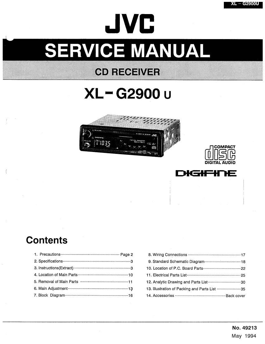
Jvc XLG 2900 Service Manual

This is the 31 pages manual for Jvc XLG 2900 Service Manual.
Read or download the pdf for free. If you want to contribute, please mail your pdfs to info@audioservicemanuals.com.

Page: 1 / 31
left right
Jvc XLG 2900 Service Manual

Extracted text from Jvc XLG 2900 Service Manual (Ocr-read)


Page 1

JVD
SERVICE MANUAL

XL- G2900 U

DIGITAL AUDIO

/ D'IG-IFl-I'I'E

Contents

1 Precautions~v~ 8. Wiring Connections .......................................... 17
2. Specifications- - 9. Standard Schematic Diagramw- --------------------- 18
3. lnstructions(Extract) - 10. Location of ROI Board Parts ------------------------------ 22
4. Location of Main Pans ---------------------------------------- 1o 11, Electrical Parts List ........................................... 25
5. Removal of Main Parts -------------------------------------- 11 12. Analytic Drawing and Parts List ------------------------- 30
6. Main Adjustment--- 13 13. Illustration of Packing and Parts List ------------------ 35
7. Block Diagram" ---16 14, Accessories ........................................ Back cover
No. 49213

May 1994

Page 2

5. Removal of Main Parts

ITop cover and bottom cover( refer to Fig. 1 )

1. Remove the screw (D retaining the top cover from the
rear panel.

2. As shown in the Figure 1. insert a screwdriver in four
spaces (a, b)between the main unit and the top cover
to release the locks.

3. All the same to 1. remove the screw (2) retainning the
bottom cover and Insert a screwdriver in four spaces (
c, d )between the main unit and the bottom cover to
release the locks.

I Front panel assembly ( refer to Fig. 1 )

1. Pull out the POWERNOLUME and FADER knohbs.

2. Use a screwdriver to release the joining sections in
four locations( e ) between the front panel assembly
and both sides of the main unit.

I Mechanism assembly ( refer to Fig. 2 , 3)

1. Dismount the pickup flexible connector CN501( in this
case, pull out the flexible connector by pushing up the
connector lock from the hole on the right side surface.
).

2. Pull out the connector CN502 on the front surface side

' of the mechanism.

3. Turn over the main unit and remove the four screws ©
retaining the mechanism assembly from the main unit.

>z flexible cord with tweezers.

I Volume P.c. board( refer to Fig.4)

1. Remove the nut retaining the volume and dismount
the volume holder.

2. Pull out the tone volume knob and remove the nut
retaining the tone volume and dismount the volume
holder.

3. Remove the two screws (9 retaining the front bracket
from the main unit.

4. Dissolder the claw of front bracket from the main PC.
board.

5. Pull out the volume P.C. board assembly in upward
direction.

6. Pull out the 6 pin connector from the connector
CN903 on the main P.C. board.

Rear side panel

XL-GZQOO U

(No. 49213) 11