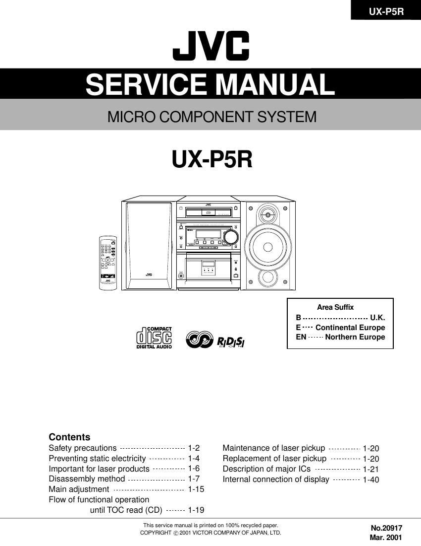
Jvc UXP 5 R Service Manual

This is the 53 pages manual for Jvc UXP 5 R Service Manual.
Read or download the pdf for free. If you want to contribute, please mail your pdfs to info@audioservicemanuals.com.

Page: 1 / 53
left right
Jvc UXP 5 R Service Manual

Extracted text from Jvc UXP 5 R Service Manual (Ocr-read)


Page 1

1-2 UX-P5R 1. This design of this product contains special hardware and many circuits and components specially for safety purposes. For continued protection, no changes should be made to the original design unless authorized in writing by the manufacturer. Replacement parts must be identical to those used in the original circuits. Services should be performed by qualified personnel only. 2. Alterations of the design or circuitry of the product should not be made. Any design alterations of the product should not be made. Any design alterations or additions will void the manufacturer`s warranty and will further relieve the manufacture of responsibility for personal injury or property damage resulting therefrom. 3. Many electrical and mechanical parts in the products have special safety-related characteristics. These characteristics are often not evident from visual inspection nor can the protection afforded by them necessarily be obtained by using replacement components rated for higher voltage, wattage, etc. Replacement parts which have these special safety characteristics are identified in the Parts List of Service Manual. Electrical components having such features are identified by shading on the schematics and by ( ) on the Parts List in the Service Manual. The use of a substitute replacement which does not have the same safety characteristics as the recommended replacement parts shown in the Parts List of Service Manual may create shock, fire, or other hazards. 4. The leads in the products are routed and dressed with ties, clamps, tubings, barriers and the like to be separated from live parts, high temperature parts, moving parts and/or sharp edges for the prevention of electric shock and fire hazard. When service is required, the original lead routing and dress should be observed, and it should be confirmed that they have been returned to normal, after re-assembling. 5. Leakage currnet check (Electrical shock hazard testing) After re-assembling the product, always perform an isolation check on the exposed metal parts of the product (antenna terminals, knobs, metal cabinet, screw heads, headphone jack, control shafts, etc.) to be sure the product is safe to operate without danger of electrical shock. Do not use a line isolation transformer during this check. Plug the AC line cord directly into the AC outlet. Using a "Leakage Current Tester", measure the leakage current from each exposed metal parts of the cabinet, particularly any exposed metal part having a return path to the chassis, to a known good earth ground. Any leakage current must not exceed 0.5mA AC (r.m.s.). Alternate check method Plug the AC line cord directly into the AC outlet. Use an AC voltmeter having, 1,000 ohms per volt or more sensitivity in the following manner. Connect a 1,500 10W resistor paralleled by a 0.15 F AC-type capacitor between an exposed metal part and a known good earth ground. Measure the AC voltage across the resistor with the AC voltmeter. Move the resistor connection to eachexposed metal part, particularly any exposed metal part having a return path to the chassis, and meausre the AC voltage across the resistor. Now, reverse the plug in the AC outlet and repeat each measurement. voltage measured Any must not exceed 0.75 V AC (r.m.s.). This corresponds to 0.5 mA AC (r.m.s.). 1. This equipment has been designed and manufactured to meet international safety standards. 2. It is the legal responsibility of the repairer to ensure that these safety standards are maintained. 3. Repairs must be made in accordance with the relevant safety standards. 4. It is essential that safety critical components are replaced by approved parts. 5. If mains voltage selector is provided, check setting for local voltage. Good earth groundPlace this probe on each exposed metal part. AC VOLTMETER (Having 1000 ohms/volts, or more sensitivity) 1500 10W 0.15 F AC TYPE ! Burrs formed during molding may be left over on some parts of the chassis. Therefore, pay attention to such burrs in the case of preforming repair of this system. In regard with component parts appearing on the silk-screen printed side (parts side) of the PWB diagrams, the parts that are printed over with black such as the resistor ( ), diode ( ) and ICP ( ) or identified by the " " mark nearby are critical for safety. When replacing them, be sure to use the parts of the same type and rating as specified by the manufacturer. (Except the JC version)

Page 2

1-3 UX-P5R 1. Service should be performed by qualified personnel only. 2. This equipment has been designed and manufactured to meet international safety standards. 3. It is the legal responsibility of the repairer to ensure that these safety standards are maintained. 4. Repairs must be made in accordance with the relevant safety standards. 5. It is essential that safety critical components are replaced by approved parts. 6. If mains voltage selector is provided, check setting for local voltage. 1. This design of this product contains special hardware and many circuits and components specially for safety purposes. For continued protection, no changes should be made to the original design unless authorized in writing by the manufacturer. Replacement parts must be identical to those used in the original circuits. 2. Any unauthorised design alterations or additions will void the manufacturer's guarantee ; furthermore the manufacturer cannot accept responsibility for personal injury or property damage resulting therefrom. 3. Essential safety critical components are identified by ( ) on the Parts List and by shading on the schematics, and must never be replaced by parts other than those listed in the manual. Please note however that many electrical and mechanical parts in the product have special safety related characteristics. These characteristics are often not evident from visual inspection. Parts other than specified by the manufacturer may not have the same safety characteristics as the recommended replacement parts shown in the Parts List of the Service Manual and may create shock, fire, or other hazards. 4. The leads in the products are routed and dressed with ties, clamps, tubings, barriers and the like to be separated from live parts, high temperature parts, moving parts and/or sharp edges for the prevention of electric shock and fire hazard. When service is required, the original lead routing and dress should be observed, and it should be confirmed that they have been returned to normal, after re-assembling. ! Burrs formed during molding may be left over on some parts of the chassis. Therefore, pay attention to such burrs in the case of preforming repair of this system. (U.K only)

Page 42

2-2 I H A BCDE FG 1 2 34 5 6UX-P5R UX-P5R Front circuit Standard schematic diagrams TAPE P.B. SIGNAL CD SIGNAL TUNER SIGNAL IC934 IC931 R7103R7342 R7341 JS731 R7252R7203 K7001 R7064 D7005 R7217R7218 R7128 R7129 R7130 R7065 R7131 D7009 C7144R7137 R7308 R7309 R7139 R7140 R7141 R7142 L7001C7136 Q7061 Q7062 R7144 IC932 C7012 R7232 B2018C7341 C7135 R7115 R7114 R7111 R7107 C7011 R7106 R7117 R7116 D7006 D7004 R7002 R7316 R7102 R7101 R7007 C7010 R7214 D7002R7003R7004 Q7041 Q7001 D7001 R7001R7215 X7001 X7002R7202 R7062R7132 R7133 D7363 R7307IC933 C7301 C7302 K7003 Q7331 C7062 C7061 R7092 R7313 R7312 R7311 C7063 R7314 R7201CN903 C7115 C7113 C7111 R7134 C7128 R7240R7239 R7145R7110 R7238R7236 R7143DI934 R7255 R7247 R7301 R7302 R7303 R7304 R7306D7362 C7149Q7092 R7254R7323 R7322 D7323 D7322 D7321 D7061 R7091 R7206 R7135CN904 C7152 R7321 D7361 C7041C7307 Q7031 C7123 R7310 R7136R7109 R7253R7108 C7108 R7138R7113 R7112Q7401 Q7402 Q7403 R7160 R7159 R7076 S7309K7002 Q7002 S7310R7125 R7126 R7127 L7003R7124 R7123 R7122 R7121 R7120R7157 S7307 C7316R7152R7151 D7007 R7008Q7003R7147 R7006 D7003R7005 D7008 C7005 C7006 C7007C7004R7148 L7002 C7002C7001 Q7091 R7043 R7093R7077 R7150 R7078 R7153 R7155 C7303 S7308C7008R7149 S7312R7146 R7331R7154 S7313 S7314 S7315R7118 R7119 B2323B2221 S7301 S7302 S7303 S7305 S7304 S7306 R7305 R7315R7221 C7009 R7075 R7042 R7041 D7332 D7331 R7332CN933 CN934 C7306 C7305 C7304CN901 S7311 C7352 C7351D7071 C7003CN900 CN902 R7079 FW931CN931 CN932D7401 D7402 D7403R7402 R7403 R7401 FW931R7158 LEDRV REM DIMMER INHRST SCDREST/OP_SW/CL_SW SAFETY0 INH REST/OP_SW/CL_SWLEDRECLEDFR RESETINH DIMMERRST MPXSPKMUTE AHB SPKMUTE SMUTE PBMUTE LINEMUTEPBMUTE REM SCDSMUTE LINEMUTE SAFETY0 NJU6433FG1 UPD78F0058GC 2.2K130K10K QSW0917-001 10K82K QQR0621-001Z 10K10K10K 2.2K 2.2K 2.2K 56K 2.2K 0.012.2K 5.6K 10K 2.2K 2.2K 2.2K 1K QQL231K-100Y100p DTC144TKA-X DTC144TKA-X2.2K KIA78S06P-T 0.1 82K100/10 100p 1K 1K 1K 1K 100/16 1K 2.2K 2.2K 10K 43K 2.2K 2.2K 47K 47K 33010K 2SC2412K/R/-X 2SA1037AK/RS/-X 1K47K QAX0410-001Z QAX0401-00110K 1K2.2K 2.2K MTZJ10C-T2 3.9KGP1U261X 47/16 0.001 QQR0621-001Z KRC111M-T 100p 150P 47K 1.2K 1K 1K 150P 100KQGF1205F1-13 100P 150P 100P 2.2K 0.001 10K10K 1K1K 10K 10K 2.2KQLD0160-001 10K 10K 1K 1K 1.2K 1.5K 2.7KMTZJ10C-T2 100P2SA1037AK/RS/-X 10K 300 300 10K 47K 2.2KQGF1205F1-16 0.001 300 MTZJ10C-T2 0.010.01 2SC2412K/R/-X 0.001 18K 2.2K1K 100K1K 100P 2.2K2.2K 2.2KDTC114EKA-X DTC114EKA-X DTC114EKA-X 2.2K 2.2K 47K QQR0621-001Z DTC114EKA-X2.2K 2.2K 12K QQL231K-4R7Y1K 2.2K 2.2K 2.2K 2.2K10K 10K 2.2K 2.2K MTZJ5.1C-T2 33K 2SC2412K/R/-X1K 100K 10K MTZJ8.2B-T20.01 18P 18P100/102.2K QQL231K-470Y 22P 20P DTC114EKA-X 100K 91K 2.2K 1K 2.2K 2.2K 0.01 2200/6.310K2.2K 1602.2K 2.2K 1K 2.2K10K 2.2/50 2.2K 390K82K 1SS133-T2 SPR-39MVWF 47QGF1205C1-04 QGF1205F1-04 0.010.01 0.01QGF1205F1-09 0.01 0.01 0.001QGF1205F1-10 22K QUM022-10Z3Z3QGF1205F1-17 QGF1205F1-17SLR-342MC-T SLR-342VC-T SLR-342MC-T200 200 200 QUM022-10Z3Z32.2K BUP PHOTOKEY1 KEY0 SCL TAPE1 SUBQ/RDDATUST/CE SDATA/VOLDA LCDCE BASS+ VOL- BASS- STTA LEDCTLVOL+ LCDCE SCK/VOLCK TAPE0 CLOSE SUBQ/RDDASQCK FTUNERSWSCK/VOLCK SDATA/VOLDAFLAG SCL MODE DATA FTUNERSW BASS- TUST/CE FTUNER VOL+ DATA LEDCTL MODE ROUT VOL- BASS+ RECL LOUTLEDREC DIMMER LEDRV LEDFR RECRPBL PBR VDD COM4 COM3 COM2 COM1 MCLK MDATA STATSEG32 SEG31 SEG30 SEG17 SEG18 SEG19 SEG20 SEG21SEG22 SEG23 SEG24 SEG25SEG26 SEG27 SEG28 SEG29 SCL DATA MODE LEDREC LEDFR STTA PHOTOMUTE MLD LCDCE +BCTL OPEN AVDD XT1 XT2RDSCK OPEN SAFETY1 BLKCK KEY0 VSS0PROTECTOR STAT SQCK SUBQ/RDDA MCLK MDATA MLD CDR POUTPOUT FCDCD+B VOLCE KEY1 CLOSE X2 CDL CDR FCD X1ROUT PRT LOUT TAPE1 CDL SEG36 TAPE0 MUTEVOLCE FTUNER CD+B BLKCK SEG1 SEG3FLAG SEG2 SEG4 SEG5 SEG6 SEG7 SEG8 SEG9 SEG10 SEG11 SEG12 SEG13 SEG14 SEG15 SEG16SEG33SEG34 SEG35 LEDRV COM1 COM2 COM3 COM4 SEG1 SEG2 SEG3 SEG4 SEG5 SEG6 SEG7 SEG8 SEG9 SEG10 SEG11 SEG12 SEG13 SEG14 SEG15 SEG16 SEG17 SEG18 SEG19 SEG20 SEG21 SEG22 SEG23 SEG24 SEG25 SEG26 SEG27 SEG28 SEG29 SEG30 SEG31 SEG32 SEG33 SEG34 SEG35 SEG36