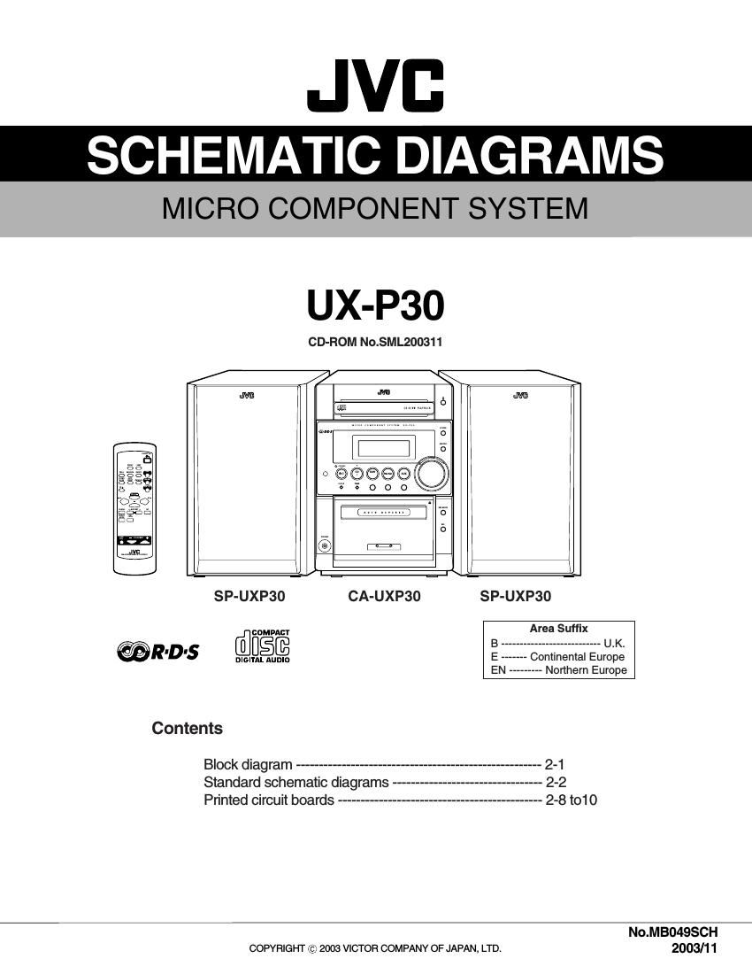
Jvc UXP 30 Schematic

This is the 14 pages manual for Jvc UXP 30 Schematic.
Read or download the pdf for free. If you want to contribute, please mail your pdfs to info@audioservicemanuals.com.

Page: 1 / 14
left right
Jvc UXP 30 Schematic

Extracted text from Jvc UXP 30 Schematic (Ocr-read)


Page 1

JVB

SCHEMATIC DIAGRAMS

MICRO COMPONENT SYSTEM

UX-P3O

CD-ROM No.SML200311

SP-UXP30 CA-UXP30 SP-UXP3O
[flcomucr Area Suffix
B --------------------------- U.K.
@RDS mmflafi E ------- Continental Europe
EN --------- Northern Europe
Contents
Block diagram ------------------------------------------------------ 2-1
Standard schematic diagrams --------------------------------- 2-2
Printed circuit boards --------------------------------------------- 2-8 to1O

No.MBO49$CH
COPYRIGHT (c) 2003 VICTOR COMPANY OF JAPAN, LTD. 2003/1 1

Page 2

In regard with component parts appearing on the silk-screen printed side (parts side) of
the PWB diagrams, the parts that are printed over with black such as the resistor (I),
diode (h) and ICP (Q) or identified by the "A mark nearby are critical for safety.

(This regulation does not correspond to J and C version.)