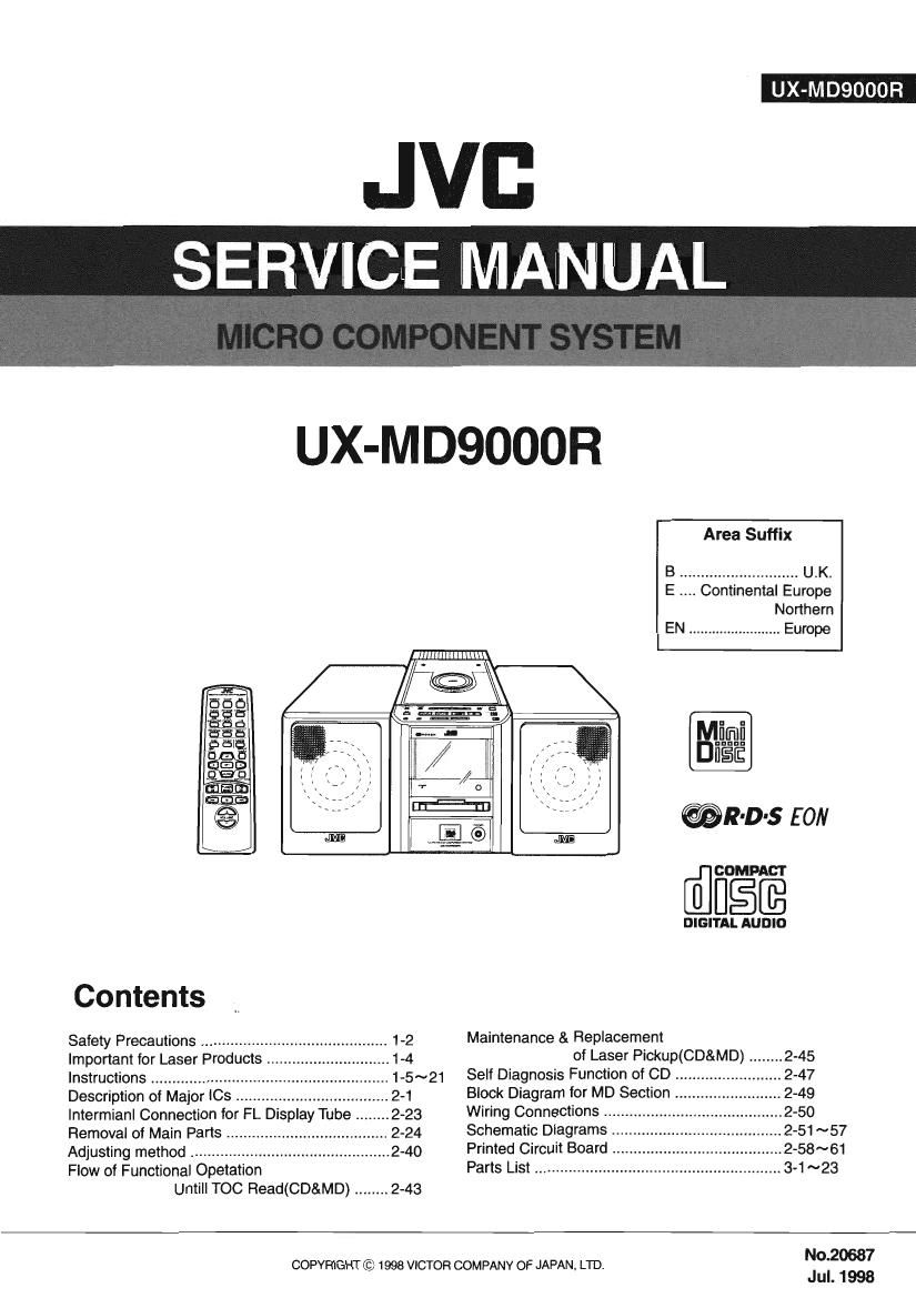
Jvc UXMD 9000 R Service Manual

This is the 124 pages manual for Jvc UXMD 9000 R Service Manual.
Read or download the pdf for free. If you want to contribute, please mail your pdfs to info@audioservicemanuals.com.

Page: 1 / 124
left right
Jvc UXMD 9000 R Service Manual

Extracted text from Jvc UXMD 9000 R Service Manual (Ocr-read)


Page 1

UX-MDQOOOR

JVB
SERVICE MANUAL

UX-MDQOOOR

"l
l

GUI

Area Suffix
B ............................ U .K.
E Continental Europe
Northern
EN ........................ Europe

E!

ufiElfls no

mg
9

IE-I

i
I!

l

@R-D-s EON

Contents

Safety Precautions ....................
Important for Laser Products .
Instructions .........................
Description ot Major le .....
Intermianl Connection for FL Display Tube . 2-23
Removal of Main Parts
Adjusting method ............
Flow of Functional Opetation

Untill TOC Read(CD&MD) ........ 2-43


COMPACT

DIGITAL AUDIO

Maintenance & Replacement

of Laser Pickup(CD&MD) ........ 2-45
Self Diagnosis Function of CD 2-47
Block Diagram for MD Section 2-49
Wiring Connections .................... ....2-50
Schematic Diagrams 2-51 ~57
Printed Circuit Board . .2-58~61
Parts List ...................... 3-1 ~23

No.20687

COPYRIGHT © 1998 VICTOR COMPANY OF JAPAN. LTD.

Jul. 1998

Page 2

-Safety Precautions

1.This design of this product contains special hardware and many circuits and components specially
for safety purposes. For continued protection, no changes should be made to the original design
unless authorized in writing by the manufacturer. Replacement parts must be identical to those
used in the original circuits. Services should be performed by qualified personnel only.

2. Alterations of the design or circuitry of the product should not be made. Any design alterations of
the product should not be made. Any design alterations or additions will void the manufacturers
warranty and will further relieve the manufacture of responsibility for personal injury or property
damage resulting therefrom.

3. Many electrical and mechanical parts in the products have special safety-related characteristics.
These characteristics are often not evident from visual inspection nor can the protection afforded
by them necessarily be obtained by using replacement components rated for higher voltage,
wattage, etc. Replacement parts which have these special safety characteristics are identified in
the Parts List of Service Manual. Electrical components having such features are identified by
shading on the schematics and by (AX) on the Parts List in the Service Manual. The use of a
substitute replacement which does not have the same safety characteristics as the recommended
replacement parts shown in the Parts List of Service Manual may create shock, fire, or other
hazards.

4.The leads in the products are routed and dressed with ties, clamps, tubings, barriers and the
like to be separated from live parts, high temperature parts, moving parts and/or sharp edges
for the prevention of electric shock and fire hazard. When service is required, the original lead
routing and dress should be observed, and it should be confirmed that they have been returned
to normal, after re-assembling.

5. Leakage currnet check (Electrical shock hazard testing)
After re-assembling the product, always perform an isolation check on the exposed metal parts
of the product (antenna terminals, knobs, metal cabinet, screw heads, headphone jack, control
shafts, etc.) to be sure the product is safe to operate without danger of electrical shock.

Do not use a line isolation transformer during this check.

0 Plug the AC line cord directly into the AC outlet. Using a "Leakage Current Tester", measure
the leakage current from each exposed metal parts of the cabinet, particularly any exposed
metal part having a return path to the chassis, to a known good earth ground. Any leakage
current must not exceed 0.5mA AC (r.m.s.)

0 Alternate check method
Plug the AC line cord directly into the AC outlet. Use an AC voltmeter having, 1,000 ohms
per volt or more sensitivity in the following manner. Connect a 1,5009 10W resistor paralleled by
a 0.1511 F AC-type capacitor between an exposed

metal part and a known good earth ground. fixgng-ER
Measure the AC voltage across the resistor with the 7 ohms/volts,

AC voltmeter. or more sensitivity)
Move the resistor connection to each exposed metal

part, particularly any exposed metal part having a 015: ACTYPE

return path to the Chasers, and measure the AC __ Place this
voltage across the resrstor. Now reverse the plug in probe on

the AC outlet and repeat each measurement voltage ' 7 each exposed
measured any must not exceed 0.75 V AC (r.m.s.). 150052 10W metal part.

This corresponds to 0.5 mA AC (r.m.s.).
Good earth ground

-Warnmg
1.This equipment has been designed and manufactured to meet international safety standards.

2. It is the legal responsibility of the repairer to ensure that these safety standards are maintained.
3. Repairs must be made in accordance with the relevant safety standards.

4. It is essential that safety critical components are replaced by approved parts.

5. If mains voltage selector is provided, check setting for local voltage.

A CAUTION Burrs formed during molding may be left over on some parts of the chassis. Therefore,
pay attention to such burrs in the case of preforming repair of this system.

Page 6

UX-M DQOOOR

«.0

.52

.5.

2...... 2.;
.232 3....
29.5.33:

.8
23.5.13
.3... SE

.6 o.
2.2% 2... 9.2.5.5 .5 3 28.5533 2.2.2.5.. 2.2.2
2.5., 2.5.25.5 2.58:8 .25... 22:8... 2... 3 282.8

wu E0 qu o 0- on atone» :: 8?: 09:6. .0 0933.0 .
.55.. 58:8 2.: > a... .8 on... .u ._._....n.. 53 $5.53.. 2o
,3: .5 9.2.5.. .322... 22:83 2... 258 8...... _a 25m
.25.... 2.... n
Em 2 cu 5.5.2:... 8.
.2. 3.2.2... 235 .2 .a 5.8... 259.... 3...... 83 oz
3:0 333- Dnsm ocwnswoog N
3.2... 28:3 52.82.89 ...m
.55.. 23.. .

2...... 2

n no. 22.3 9... .35. .5 ..m 85!. .o 25.
$3 .. 22.8... 0 $228.» .8588 8 o
84...... :28.

52:... 2.8...

.o .5 E .5. E- .u... 5.23.... E. 9. 1...... .2 58 .5.

ex. 2...... .2. .3392. 2:52. 5.29.8.5 1.2. no
2.3.2.5 n

.38.

$32.: 522.... mu .. 53...... 52.2.5.2... .55
.5...2...2...£8..§..~..n a
2...: 22.8%.. .5 .8255222 55

3-.) Eat

.5252 .u 355...: x... 2.9.. an... :2.
Aim .5 Sn Ewan-A 3 cc BE in was: 33:09: I. In 2.5
8 a 5.2. 2.5.2.5.. .» 2:... 8...... £5 5. _ 5....
$3032. 0
53%.... 2.2.8
.. 5. £529.. .83: .2 3.3... 2. 5.. 2... 2.3552
acidosflfiuaaiflbu N
.22. .8. 8 1.3% ..2m
2.5.2 .
2.2.5. 225... s 3 :28... 5.22.. 22.22.23 2525......
s 2.5.8.2.: 8 2.2.52. $.28 8 9...... :6. 2:22.. .31
33:8 :25: 2.3.5.:


(a... .59 2.2
58...... 5.. 2.5 Eu...» .5» 5.2.223 .65.. 22.5.3 922...
22..» 5 gm .593 s... .3. 5.2... .5... 25.5% a...
3. 5...: o
$52.55. 2 .55....5 Easing .5... 5 .93.. ..x
.8533 v.5 5.5m m
£359: 5.. v.5 5.32.8.2:
2.3.22.5 .
2.8.2.
. 2...... (vacation .8392 .2... .23 2... 2 53in
52.2.8 5... .2... ...%......m 552.22. is 952 S 3
9.35.3 85:22.3 . 5.22.

.22.. a .5 a. 5 2a.... . 5.; 2.2. .. ..... 8.3. .s 8....
2...... a. 5!. .i 259-...- ..u Essa: 8.2.5 15 a... .6 82a.
.55 m
.303 «5225
In. >5 5.6: all... .5 c. csfla on SEEM gin oz
2.3 3... 3% w
.9293» :80 93 SUE-mac oz
EEK -
25...... 2 5.239. 3..
28°. .832. 52.2. 2 a... a... e... .8... 8.25 .o .2. 5.. fl
=u.i.=.s> .32. 225.0

22.5....- o guano... s... 028339.. 29.83 S: m
228.. 2 o $.38 ..._> 22.8. 82 .
. as .28... .853 as... .u 262. _. $53. .wm
5.8sz..

5.3.5... 2 a e 2... E 2.5% 2.. sagas .2 N

13 2 E .2. s. 25.5 oz .
H u.» 66:03: .mdfl.5¢_u ad :0 an mama: 20:3. Emu
20.23qu

3......
. E. 5.22 .
ufizonxog

TO

2.2.5.... a E 22.. q. a 5.5.9.. .32.... m... .z m
.6595 on .2.
.8 2 2.2.0 as. 2. S .5255. B. E as um. .25.... a... .z .
.2. 6.9.8.... 5830.629... 2&2. .2. .225... ....<
zoczmt<

.colammja =32503ak so: camel .0 vi .960 wwon .N
V... .5 22.. 8......5
.2. a... ......2_... 5956...? a? .32.. 52.2%» 2.3. .
3.. 22.9.5... .323 5.3.x... :2 9552...... 5
2.2.23

3 8.21% 2... 38.8 .2. on .N
228 $23 22.... .2. on V.

. .18... .2562» .a .2. 2.. 85.2 5

29.5.6

.333

5.. .8: 5.2.2. «2.5.50 5 m 0...: 5.33m. 25. 28

3.. 2.2. 3.... 2.8 225....22... ... EN. .8 2.1 2 2.5235.
. 5... 22:53:... | 5.2.3...

222.22.... 322.
m 5 guanine... 2.5.5

-23 .53.
25.2.5.3.
5.92:2.

.2355»... .. 2.8 ESESEEEE 2. .u... .8 523% .2.
z... 2 fission .5. S .9 2.3. 8 53.93 5%. .339. .2.
a... 58..» 92.3.39. music .3 .2...» .o E 28.3 55:93...
.2. .5 is; a... .. 12.52%... a 2.1. 30525025 3 ...o
3.28 5 | 222:8:

«952.58.: 2. 5... .558 a. 5.23..
555% an 2.9. a. $052.58 «.25... 3:8 9. _ 55.258 a.
,........8 2... 3.58 i=3 5.... .522: S 2. 552525

.5 5553.556 | 5.2.3.1

on 26 £3...


.33; 5.2.3325 E... 2... 95.5335». .8 i. 5.5.
mc5yoea§9fi 29 5.5.5.... 23.3.3.5..m o... 9.2.3
5...... 2 $5.52.... 5 2.23 .3 $5222.... a 525...?
Ezrugizem a... .5 22.2N $8555 .2. 2.» 55.233. .8

.. :3. .5. I 95.5..

. :00 0.9:? on :8
.9263 9C. 6:: WEE: 05 50553.6 5: ma ion PM E $2.5
2.. 2: 222.58 .5 52.... 2.. .2... 2 m5... 2. 2.. 52.535

2...:- 5 | .555

25:38 at Eofiauoaa a 022.023 \ $3: 3.8 > 3:20:82: £02.55???
.3... 22:5 .5 593.69 50553352qu 3952... 22.365 .o 30.5.32; .223
.5 non-2 3335: 095:3 cc: 9.3:; 6.5535 \ 2050 ten ace-.300 £552.53

1-6

Page 37

UX-MDQOOOR

Pin No. Symbol l/O Function
51 ASYO O Playback EFM full-swing output. (Low2Vss High:Vdd)
52 ASYI I Playback EFM comparator slice voltage input.
53 AVdd - Analog power supply.
54 BIAS I Playback EFM comparator bias current input.
55 RFI I Playback EFM RF signal input.
56 AVss - Analog ground.
57 PDQ 0 Phase comparison output lor analog PLL ol EFM decoder.
58 PCO 0 Phase comparison output for master PLL of playback digital PLL and recoding EFM PLL.
59 FlLl I Filter input for master PLL of playback digital PLL and recording EFM PLL.
60 FILO 0 Filter output for master PLL of playback digital PLL and recording EFM PLL.
61 CLTV I Internal VCO control voltage input for master PLL of playback digital PLL
and recording EFM PLL.
62 PEAK I Peak hold signal input for quantity of light.
63 BOTM I Bottom hold signal input for quantity of light.
64 ABCD I Signal input for quantity oi light.
65 FE I Focus error signal input.
66 AUX1 I Auxiliary input1.
67 VC l Center voltage input.
68 ADIO 0 Monitor output for A/D converter input signal,
69 AVdd - Analog power supply.
70 ADHT | Voltage input for the upper limit of the A/D converter operating range.
71 ADRB l Voltage input for the lower limit of the AID converter operating range.
72 AVss - Analog ground.
73 SE I Sled error signal input.
74 TE | Tracking error signal input.
75 AUX2 | Auxiliary input 2.
75 DCHG I Connect to the low-impedance power supply.
77 TEST4 I Error signal input for laser digital APC.
78 ADFG l ADlP binary FM signal (22.05i1kHz) input.
79 FOCNT O CXA2523 current source setting output.
80 XLRF O CXA2523 control latch output. Latched at the falling edge.
81 CKRF O CXA2523 control shift clock output.
82 DTRF O CXA2523 control data output.
83 APCREF 0 Reference PWM output for laser AFC.
84 TESTO - Non connect
85 TFtDFt 0 Tracking servo drive PWM output.( - )
86 TFDFt 0 Tracking servo drive PWM output.( + )
87 DVdd - Digital power supply.
88 FFDR 0 Focus servo drive PWM output.( +)
89 FRDR 0 Focus servo drive PWM output.( - )
90 F84 - Non connect.
91 SRDR O Sled servo drive PWM output.( - )
92 SFDR O Sled servo drive PWM output.( + )
93 SPRD O Spindle servo drive output.(PWM(-) or polarity)
94 SPFD O Spindle servo drive output.(PWM(+) or PWM absolute value)
95 FGIN I Spindle CAV servo FG input.
96 TEST1 l Test pin.Connect to GND.
97 TEST2 l Test pin.Connect to GND.
98 TESTS l Test pin.Connect to GND.
99 DVss - Digital ground.
100 EFMO 0 Low when playbacszFM (encoded data) output when recording.

2-15

Page 49

IRemoving CD Servo control P.C.Board
(see Fig.15 and Fig.16)

1. Remove the CD player assembly from the body.

2. Remove the tour screws @ attaching CD Servo control
P.C.Board in the bottom of CD player assembly.

3. Disconnect the card wire from connector CN601 on CD
Servo control P.C.Board.

4. Disconnect the harness from connector P011 on Motor
P.C. Board.

CD Servo control

P.C.Board
lRemoving CD mechanism assembly
' CD mecha
(see Fig.1?) bracket
1. l bod .
Remove CD p ayer assembly from the y Damper

2.Remove CD Servo control P.C.Board from CD player
assembly.

3. Remove the four screws ® attaching CD mechanism
assembly.

4. Remove the tour dampers and CD mechanism bracket
from CD mechanism assembly.

lRemoving CD Motor drive P.C.Board
(see Fig.17 and 18)

1. Remove CD player assembly from the body.

2. Remove CD Servo control P.C.Board from CD player
assembly.

3. Remove CD mechanism assembly.
4. Flemove the loading belt.

5.Remove the two screws ® attaching CD door Motor
drive P.C. Board.

UX-MDQOOOR


CD player
/ assem ly

CD Servo control
P.C.Board

Fi9'15 CN601


CD mechanism
assembly

Damper

CD door Motor
P.C.Board

Loading belt

2-27