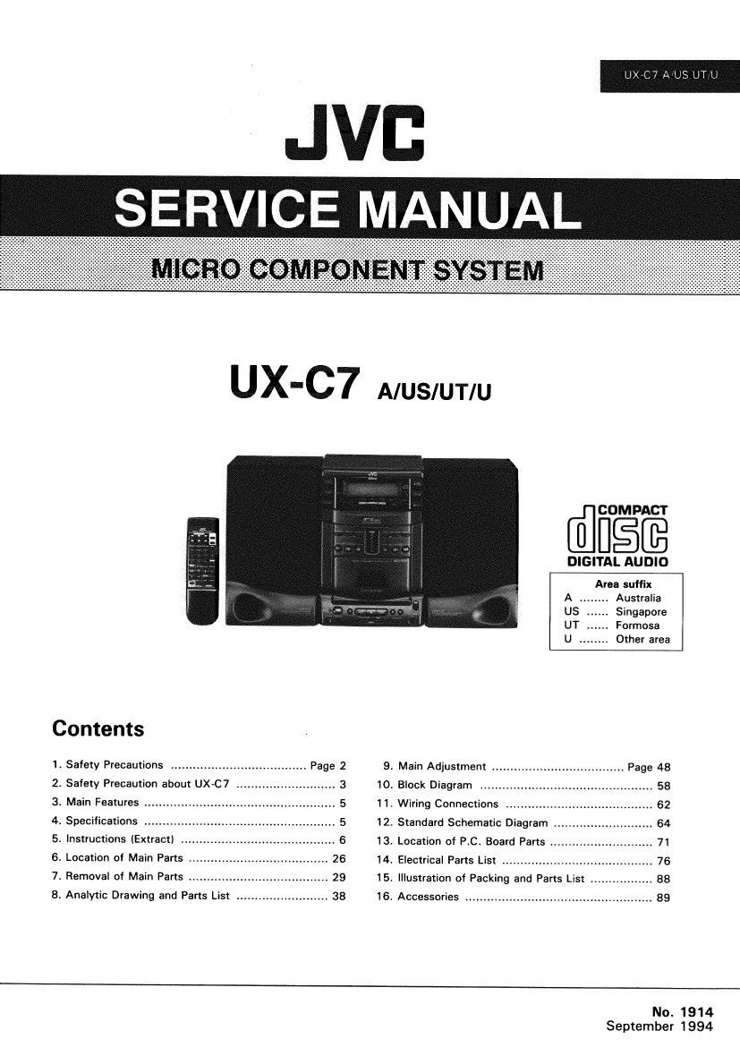
Jvc UXC 7 Service Manual

This is the 108 pages manual for Jvc UXC 7 Service Manual.
Read or download the pdf for free. If you want to contribute, please mail your pdfs to info@audioservicemanuals.com.

Page: 1 / 108
left right
Jvc UXC 7 Service Manual

Extracted text from Jvc UXC 7 Service Manual (Ocr-read)


Page 1

Contents

1. Safety Precautions ..................................... Page 2
2. Safety Precaution about UX-C7 ........................... 3
3. Main Features .................................................... 5
4. Specifications .................................................... 5
5. Instructions (Extract) ., 6
6. Location of Main Parts .. 26
7. Removal of Main Parts ................... .. 29
8. Analytic Drawing and Parts List ......................... 38

9.
10.
11.
12.
13.
14.
15.
16.

[flfigffé

DIGITAL AUDIO
Area suffix
A ........ Australia

Singapore
Formosa
Other area


Main Adjustment .

Block Diagram

Wiring Connections ........................................ 62
Standard Schematic Diagram ........................... 64
Location of P.C. Board Parts ............................ 71
Electrical Parts List .......................... 76
Illustration of Packing and Parts List .. . 88
Accessories ................................................... 89

No. 1914
September 1994

Page 2

UX-C7 A/US/UT/U

2

1. Safety Precautions

. The design of this product contains special hardware and many circuits and components specially tor safety purposes. For continued

protection. no changes should be made to the original design unless authorized in writing by the manufacturer. Replacement parts
must be identical to those used in the original circuits. Service should be performed by qualified personnel only.

. Alterations of the design or circuitry of the product should not be made. Any design alterations of the product should not be made. Any

design alterations or additions will void the manuiactures warranty and will lurther relieve the manufacture oi responsibility lor personal
injury or property damage resulting therefrom.

. Many electrical and mechanical parts in the products have special safety - related characteristics. These characteristics are often not

evident lrom visual inspection nor an the protection aitorded by them necessarily be obtained by using replacement components rated
lor higher voltage. wattage. etc. Replacement pans which have these special safety characteristics are identified in the Parts List of
Svervice Manual. Electrical components having such features are identified by shading on the schematic and by ( A )on the Parts
List in the Service Manual. The use oi a substitute replacement which does not have the same safety characteristies as the

recommended replacement part shown in the Parts List oi Service Manual may create shock. fire. or other hazards.

.The leads in the products are routed and dressed with ties. clamps . tubings. barriers and the like to be separated from live parts. high

temperature parts, moving parts and [or sharp edges for the prevention of electric shock and fire hazard. When service is required. the
original lead routing and dress should be observed. and it should be confirmed that they have been returned to normal. after
reassembling.

. Leakage current check (Electrical shock hazard testing)

After reassembling the product. always perform an isolation check on the exposed metal parts of the product (antenna terminals.

knobs. metal cabinet. screw heads, headphone jack. control shafts. etc.) to be sure the product is safe to operate without danger of

electrical shock Do not use a line isolation transformer during this check.

- Plug the AC line cord directly into the AC outlet Using a Leakage current testef'. measure the leakage current from each exposed
metal part oi the cabinet. particulary any exposed metal part having a return path to the chassis. to a known good earth ground. Any
leakage current must not exceed 0.5mA AC(r.m.s.).

AC VOLTMETER
-Altemate check method 63 (Having 1°00 ohms/volt,
Plug the AC line cord directly into the AC outlet. Use an AC °""°"""V"Y-
voltmeter having. 1.000 ohms per volt or more sensitivity in the _"__J

following manner. Connect a 1.500 ohms 10W resistor paralleled by 015 "F AIC Type

a 0.15 p. F AC type capacitor between an exposed metal part and a

Plea: this probe
known good earth ground. Measure the AC voltage across the A on "ch "90in
1500 n 10W metal part.

resistor with the AC voltmeter. Move the resistor connection to each
exposed metal part, particularly any exposed metal part having a 6° ""h ground
return path to the chassis. and measure the AC voltage across the resistor. Now. reverse the plug in the AC outlet and repeat each

measurement. Any voltage measured must not exceed 0.75V AC(r.m.s.).This corresponds to 0,5mA AC(r.m.s.).

The lightning flash with arrowhead symbol,

within an equilateral triangle, is incur-dad to

CAUTION alert the user to me presence or uninsullted
Rsrmttrmlcsiioot "dangerous voltage" within the product's
m mi MN enclosure that may be or sufficient magni-

tude to constitute a risk of electric shock ro
persons.

CAUTION: to amuse m5 RISK OF ELEcrr-uc snocx,
00 N01 REMOVE COVER (on men. The exclamation point within an equilateral
NO USER-SERVICEAELE PARYS WS'PE- triangle is intended to alert the user ID the
REFER SERVICING TO QUALIFIED SERVlCE PERSONNEL. pm, a) 5,"me wanting d main-
tenance (mining) instructions in the litera-
ture accompanying me appliance.

(No. 1914)

Page 18

UXC7 A/US/UT/U

( RECORDING 4
-
' a
a

a in recording, the ALC circuit automatically optimizes the
recording level; adjustment of the recording level is
unnecessary.

0 Check that the safety tab on the cassette tape is not
broken off.

Notes:

This unit has recording characteristics suitable for normal
and Cr02 tapes. Normal and 002 tapes have different
characteristics from metal taper

DOLBY NR SYSTEM

C Set the DOLBY NR as required. The DOLBY NR
indicator lights.

Note:

The optimum sound quality will not be obtained if different
DOLBY NR switch settings are used during recording and
playback.

It may be unlawful to record or playback copyrighted
material without the consent of the copyright owner.

Erasing

When recording on a pre-recorded tape, the previous
recording is automatically erased and only the new material
can be heard when the tape is played.

To erase a tape without making a new recording...

Press the I (stop) button to set to the TAPE mode, then
perform recording.

Synchronized recording with the CD player

0 in this system, the CD player starts playback when the
cassette deck enters "to recording mode.

Operate in the order shown

(Recording from the CD changer)

18 (No. 1914)


we may

WM/

Cilia

0 Press the DISC CONTROL button corresponding to the
disc to be recorded.
0 Press the IICLEAR button to set stop mode.
0 Load a cassette with side A facing out. (Wind past the
leader tape before starting recording.)
a When programmed playback is required, program the
geaqrired tunes using the remote control. (See page
I Select tunes with a total playing time which does not
exceed the tape length,
0 Select the required reverse mode ( : or 2) )
0 Set the DOLBY NFt switch as required
6 Press the SYNCHRO REC button; synchronized
recording will start.

0 Recording starts in the forward direction and CD play
stans automatically.

0 When the CD player has played the disc or programmed
tunes, the deck stops automatically.

0 Non-recorded sections of approx. 4 seconds are
automatically left between tunes.

I TIo stop recording, press the l/CLEAR button of the CD
p ayer.

(Recording from the EXTRA-CD)
Load the EXTRA-CD and press the I/CLEAR button to set
stop mode, and press the SYNCHRO REC button

When automatic spacing between tunes is not

required

Perform the following.

1 . Press the l>/ll button of the CD player twice. The CD
Player enters the pause mode.

2. Press the SYNCHRO REC button to start recording.

Note:
0 Depending on the disc used, blanks of a specified
length may be left between tunes.

CD complete recording function (Synchro recording
mode only)

If the tape is reversed while a CD is being played, recording
will be done on the reverse side of the tape as follows:

When less than 12 seconds of the last tune on the
forward side of the tape have been recorded. recording
on the other side of the tape will start from the beginning
of the previous tune.

When more than 12 seconds of the last tune on the
forward side of the tape have been recorded, recording
on the other side of the tape will start from the beginning
of the current tune.

To record an entlre disc in the tune order of the CD
After the operations in steps 0 - 0 above, press the l>lll
button of the CD player after the .III and l> buttons have
been pressed.

Note:
0 During synchro recording, the l>lll and SEARCH
buttons do not function.

Page 34

UX-C7 A/US/UT/U

l Method of removing the cassette mechanism
control P.C. board and Dolby amplifier P.C.
board (Refer to Fig. 7-19)

1. Remove the CD fitting (Refer to Item 1 of "Method
of removing the CD changer mechansim as-
sembly).

2. Remove the top cover (Refer to "Method of remov-
ing the top cover").

3. Remove the system microcomputer P.C. board
(Refer to "Method of removing the system
microcomputer RC. board").

4. Remove the rear panel assembly (Refer to
"Method of removing the rear panel assembly).

5. Remove the CD changer mechansim assembly
(Refer to Item 2 and subsequent paragraphs of
Method of removing the CD changer mechansim
assembly).

6. Remove the front panel assembly (Refer to
"Method of removing the front panel assemblY).

7. Remove the cassette mechanism assembly and
door holder assembly (Refer to "Method of remov»
ing the cassette mechanism assembly and door
holder assembly).

8. From the cassette mechanism assembly, remove
the four screws (21 )< 2 and 22 X 2) retaining
the cassette mechansim control P.C. board and Dol-
by amplifier P.C. board.

9. After respectively removing the connectors CN342
and CN343 on the Dolby amplifier P.C. board,
CN322 on the bias OSC P.C. board and CN851 on
the cassette mechanism control P.C. board, dis-
mount the Dolby amplifier P.C. board.

I Method of removing the preamplifier P.C.
board and bias OSC P.C. board
(Refer to Fig. 7-20)

1. Refer to the procedures in Item 1 through Item
10 on page 33.

2. From the connector CN301 on the preamplifier
P.C. board, remove the flexible print card
outgoing from the recording and playing head.

3. From the cassette mechanism assembly,
remove the one screw retaining the pre-
amplifier P.C. board.

4. After moving the preamplfier P.C. board, remove
the protruding portion @ of the mechanism
from the notched groove on the P.C. board.

5. From the bracket, remove the two screws
retaining the preamplifier P.C. board.

6. Remove the connectors CN303 on the pre-
amplifier P.C. board and CN321 on the bias OSC
P.C. board.

7. From the bracket, remove the one screws @
retaining the bias OSC P.C. board.

34 (Na 1914)

10. While raising the cassette mechanism control P.C. board, remcwe the
P.C. board respectively from the connectors CN852, CN853 and CN855
on the cassette mechanism control P.C. board, connector CN2 on the
reel motor P.C. board, connector cm on the leaf switch PC. board and
connector CN302 on the preamplifier P.C. board.

Cassette mechansim
control P.C. board

Preamplifier
P.C. board

CN302


Leaf switch
P.C. board

CN2

Dolby amplifier P.C. board

Bias OSC P.C. board

Fig. 7.19

Flexible print card


Preamplifier

CN303
CN321
CN301 Bias OSC P.C. board