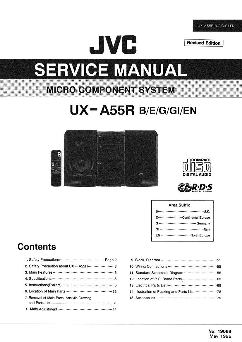
Jvc UXA 55 R Service Manual

This is the 108 pages manual for Jvc UXA 55 R Service Manual.
Read or download the pdf for free. If you want to contribute, please mail your pdfs to info@audioservicemanuals.com.

Page: 1 / 108
left right
Jvc UXA 55 R Service Manual

Extracted text from Jvc UXA 55 R Service Manual (Ocr-read)


Page 1

RBEGGEN

SERVICE MANUAL

UX- A55R B/E/G/GI/EN

[flfifififi

DIGITAL AUDIO
@RDS
Area Suffix
B .......................................... UAKi
E ---------------------- Continental Europe
G .. Germany
GI . mummy
EN --------------------------- North Europe
Contents
1. Safety Precautions -------------------------------------- Page 2 9. Black Diagram ................................................ 51
2. Safety Precaution about UX - A55R ----------------------- 3 1o. Wiring Connections ------------------------------------------ 55
3. Main Features ----------------------------------------------------- 5 11, Standard Schematic Diagram ............................ 55
4. Specifications- 12. Location of RC. Board Paris:
5. Instructions(Extract) --------------------------------------------- 5 13. Electrical Parts List .................
6. Location of Main Parts ---------------------------------------- 26 «[4, Illustration of Packing and Fans 5 ................... 78
7. Removal of Main Parts. Analy1ic Drawing 15. Accessories -------------------------------------------------- 79

and Paris Lisi

3. Main Adjustment-~

No. 19068
May 1995

Page 2

2

UX-A55R B/E/G/GI/EN

-1. Safety Precautions

1. The design of this product contains special hardware and many circuits and components
specially for safety purposes. For continued protection, no changes should be made to the
original design unless authorized in writing by the manufacturer. Replacement parts must
be identical to those used in the original circuits. Services should be performed by
qualified personnel only.

2. Alterations of the design or circuitry of the product should not be made. Any design
alterations of the product should not be made. Any design alterations or additions will
void the manufacturer's warranty and will further relieve the manufacture of responsibility
for personal injury or property damage resulting therefrom.

3. Many electrical and mechanical parts in the products have special safety-related
characteristics. These characteristics are often not evident from visual inspection nor can
the protection afforded by them necessarily be obtained by using replacement components
rated for higher voltage, wattage, etc. Replacement parts which have these special safety
characteristics are identified in the Parts List of Service Manual. Electrical components
having such features are identified by shading on the schematics and by (A) on the Parts
List in the Service Manual. The use of a substitute repalcement which does not have the
same safety characteristics as the recommended replacement parts shown in the Parts List of
Service Manual may create shock, fire, or other hazards.

4. The leads in the products are routed and dressed with ties, clamps, tubings. barriers and
the like to be separated from live parts, high temperature parts, moving parts and/or sharp
edges for the prevention of electric shock and fire hazard. when service is required, the
original lead routing and dress should be observed, and it should be confirmed that they
have been returned to normal, after re-assembling.

5. Leakage currnet check (Electrical shock hazard testing)
After re-assembling the product, always perform an isolation check on the exposed metal
parts of the product (antenna terminals, knobs, metal cabinet, screw heads, headphone jack,
contorl shafts, etc.) to be sure the product is safe to operate without danger of electrical
shock.
Do not use a line isolation transformer during this check.

0 Plug the AC line cord directly into the AC outlet. Using a "Leakage Current Tester,
measure the leakage current from each exposed metal parts of the cabinet, particularly
any exposed metal part having a return path to the chassis, to a known good earth
ground. Any leakage current must not exceed 0.5mA AC (r.m.s.).

0 Alternate check method
Plug the AC line cord directly into the AC outlet. Use an AC voltmeter having, 1,000
ohms per volt or more sensitivity in the following manner. Connect a 1,5000 10 W
resistor paralleled by a 0.15 F AC-type capacitor between an exposed metal part and a
known good earth ground.

AC VOLTMETER

Measure the AC voltage across the resistor E (Having 1000
With the AC voltmeter. ohms/volts, .
Move the resistor connection to each exposed 0 °_ 0' more SGHSINVIWJ
metal part, particularly any exposed metal part
having a return path to the chassis, and 9,15,; AC Type
meausre the AC voltage across the resistor. [-
Now, reverse the plug in the AC outlet and a "5
A. probe on
repeat each measurement. Any voltage - - "v each exposed
measured must not exceed 0.75 VAC (r.m.s.). 15009 W metal part.
This corresponds to 0.5 mA AC (r.m.s.). Good eaflh ground

-Warning

1. This equipment has been designed and manufactured to meet international safety standards.

2. It is the legal responsibility of the repairer to ensure that these safety standards are
maintained.

3. Repairs must be made in accordance with the relevant safety standards.
4. it is essential that safety critical components are replaced by approved parts.
5. if mains voltage selector is provided, check setting for local voltage.

(No. 19063)

Page 22

UX-ASSR B/E/G/GI/EN

0 It you select TRAFFIC, the unit will stop searching
when it finds a broadcast carrying traltic
announcements. However, this does not
necessarily mean that you can listen to a traffic
announcement at that time. Rather it means that

you will get it when it is broadcast.

RECORDING m
<- no

I}

O In recording. the ALC circuit automatically «optimizes the
recording level: adjustment of the recording level IS

unnecessary.

0 Check that the safety tab on the cassette tape is not

broken off.

Notes:

This unit has recording characteristics surtable for normal
and CrOz tapes. Normal and 0102 tapes have ditlerent

characteristics trom metal tape.

CD edit recording (tor CDs with up to 20 tunes)

0 By checking the total playing time of the CD. a
microcomputer in the unit automatically calculates the
optimum length (recording time) of the tape to be used.
displays the required tape length, and divides the tunes
on the disc into two groups to be recorded on the two

sides of the tape so as to minimize tape waste.

Operate in the order shown

m5 EVE' 50m 515
I-l H

18 (No. 19063)

0 Press to open the CD door. (The power IS swrtched on.)
0 Load a disc and press to close the CD door.

0 Set to the CD mode.

0

Press the EDIT button while pressing the SHIFT button.

EE®

SHIFT son

an». 9%..»- The lune numbers
,- I' U U (9 recorded on sideA
/_ :I I appear.

9 Press the SIDE A/B button while pressing the SHIFT
button.

/Thetunenumbers

93:} reoordedon side 3
I ' Q r.
,_ - '-, '-/ 8s» W

0 Insert a cassette with a suitable length (recording time)
with side A facing out.

I Thetape length can be set from the remote control.
(See below.)

0 Press the CD SYNCHFtO REC button to start CD edit
recording.

0 Recording starts in the forward direction (on the side
facing out).

0 During edit recording. the leader tape section
(approx first 10 sec.) is wound automatically and
then recording starts. The reverse mode is set to
:3 mode automatically.

0 The tape stops automatically when the CD has been
played.

0 To change the tape length (recording time)
When the EDIT button is pressed while pressing the
SHIFT button with a CD loaded. the tape length required
to record the entire disc is displayed (0-46. 054, 0-60,
0-74 or (>90).
At this time, the displayed tape length can be changed
by pressing the track number buttons.

Example: To change to 6-50

Press the +10 button four times. and within 10 seconds
press the 10 button.

When the length of the tape is changed. some of the tunes
that were to be recorded on side A may be indicated as to
be recorded on side 8 or vice versa, according to the tape
length specified.

Depending on the tape length specified, some tunes may
not be recorded on the tape. Set the tape length (recording
time) so that the entire disc can be recorded.

0 When editing a dlsc with 16 to 20 tunes

CD editing can be used to record discs containing up to
20 tunes. however. the music calendar shows up to only
15 tunes.

As the 16th to 20th tunes will not appear in the music
calendar display (the "OVER indicator will light), be sure
to check the tunes you have recorded after completing
editing.