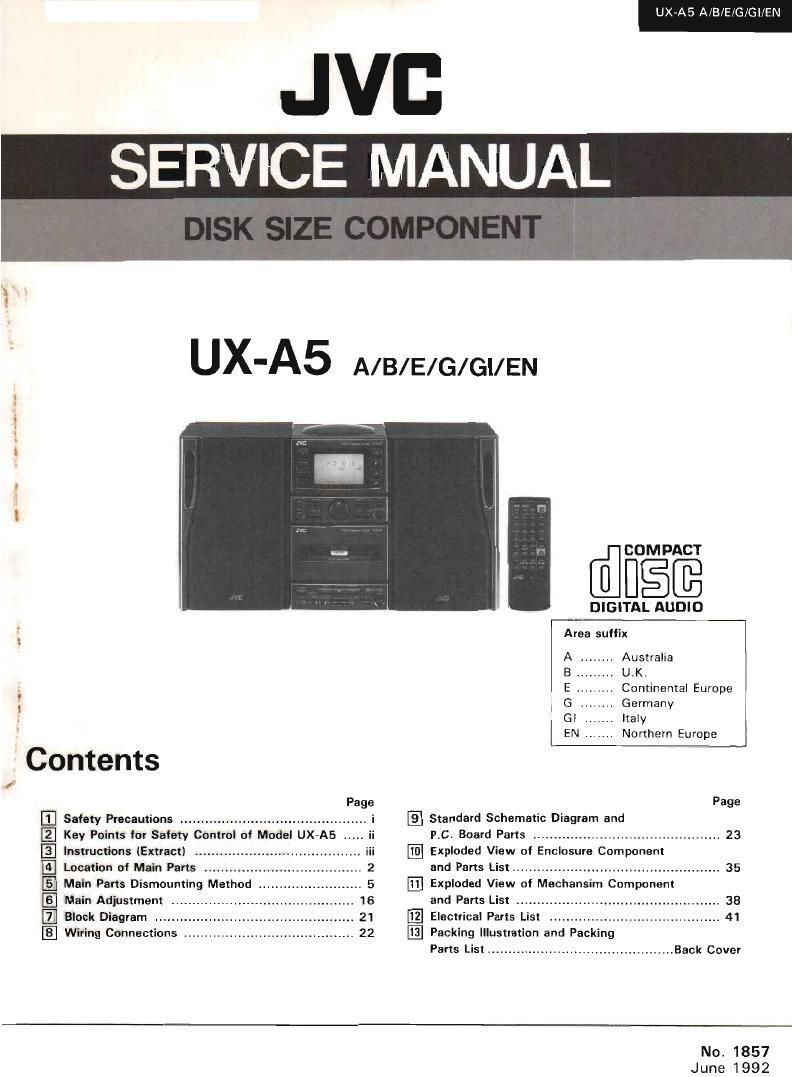
Jvc UXA 5 Service Manual

This is the 80 pages manual for Jvc UXA 5 Service Manual.
Read or download the pdf for free. If you want to contribute, please mail your pdfs to info@audioservicemanuals.com.

Page: 1 / 80
left right
Jvc UXA 5 Service Manual

Extracted text from Jvc UXA 5 Service Manual (Ocr-read)


Page 1

JVI:
SERVICE MANUAL

UX-AS A/Bl'E/G/GUEN

.V - ~....»~

r
l
.
r

UX'A5 A/B/E/G/GI/EN

' Contents

4

filfigfi

DIGITAL AUDIO

y_- _
Area suffix

A ........ Australia

E . Continental Europe
G ...... Germany

GI . . Italy (
EN . . Northern Europe

A Page Page
Ii] Safety Precautions ............................................. i [El Standard Schematic Diagram and
[2] Key Points for Safety Control of Model UX-A5 ' P.C. Board Parts ............................................. 23
[El Instructions (Extract) Exploded View of Enclosure Component
[E Location of Main Parts ......... .. 2 and Parts List .................................................. 35
[E] Main Parts Dismounting Method . 5 Exploded View of Mechansim Component
IE] Main Adjustment and Parts List ......................
Block Diagram El Electrical Parts List ..............
Wiring Connections El Packing Illustration and Packing

Parts List ............................................. Back Cover

No. 1857

June 1992

Page 2

UXVAE A/B/E/G/Gl/EN J

. 1 Safety Precautions

1. The deSign of this product contains special hardware and many circuits and components specially for safety
purposes. For continued protection, no changes should be made to the original design unless authorized in writing
by the manufacturer. Replacement parts must be identical to those used in the original circuits. Service should
be performed by qualified personnel only.

. 2. Alterations of the desrgn or circuitry of the product should not be made. Any design alterations of the product
should not be made. Any design alterations or additions will void the manufacturer's warranty and will further

relieve the manufacturer or responsibility for personal injury or property damage resulting therefrom.

3. Many electrical and mechanical parts in the product have special safety-related characteristics. These
characteristics are often not evident from visual inspection nor can the protection afforded by them necessarily
be obtained by using replacement components rated for higher voltage, wattage, etc. Replacement parts which
have these special safety characteristics are identified in the Parts List of Service Manual. Electrical components
having such features are identified by (A) on the schematic diagram and Parts List in Service Manual The use
of a substitute replacement which does not have the same safety characteristics as the recommended replace
ment part shown in the Parts List in Service Manual may create shock, fire, or other hazards.

4, The leads in the products are routed and dressed with ties, clamps, tubings, barriers and the like to be separated
from live parts, high temperature parts, moving parts andlor sharp edges for the prevention of electric shock
and fire hazard.

When service is required, the original lead routing and dress should be observed, and it should be confirmed
that they have been returned to normal, after re-assembling.

5. Leakage current check (Electrical shock hazard testing)

After rte-assembling the product, always perform an isolation check on the exposed metal parts of the product
(antenna terminals, knobs, metal cabinet, screw heads, headphonejack, control shafts, etc.) to be sure the pro-
duct is safe to operate without danger of electrical shock.

Do not use a line isolation transformer during this check.

- Plug the AC line cord directly into the AC outlet. Using a Leakage Current Tester", measure the leakage

current from each exposed metal part of the cabinet, particularly any exposed metal part having a return path

to the chassis, to a known good earth ground. Any leakage current must not exceed 0.5 mA AC (r.m.s ).

i 0 Alternate check method

Plug the AC line cord directly into the AC outlet. Use an AC voltmeter having 1,000 ohms per volt or more
sensitivity in the following manner. Connect a l,500 910 W resistor paralleled by a O 15 [.LF ACrtype capacitor

between an exposed metal part and a known good earth ground. [ AC VOLTMETER
Measure the AC voltage across the resistor with the AC r" i 3 (Having 1000 ohms/volt
voltmeter. I

or more sensitivity l

Move the resistor connection to each exposed metal

part, particularly any exposed metal part haying a return w ;

path to the chassis, and measure the AC voltage across l 0'15 A YPE
the resistor. Now, reverse the plug in the AC outlet and F l f ' i Place this robe
repeat each measurement. Any voltage measured must 1 . M4_ri D on each 9:)pr i
not exceed 0.75 V AC (r.m.s). 1500 t) 10 W metal part.

This corresponds to 0.5 mA AC (r.m.s.) "4
Good earth ground

e Warning -e _-e 7-- e#i_a

. This equipment has been designed and manufactured to meet international safety standards.

. it is the legal responsibility of the repairer to ensure that these safety standards are mainteined.
. Repairs must be made in accordance with the relevant safety standards.

. it is essential that safety critical components are replaced by approved parts.

. lf mains voltage selector is provided, check setting for local voltage.

(fiwa-i

Page 22

UX»A5 A/B/E/G/Gl/EN

Timer playback

I Timer playback of tapes, broadcasts and CBS is
possrble,

Operations

0 Set the POWER switch to ON. _
0 Set the timer start and stop llmes. set the timer
playback mode, then set the volume, in this order.

Source sound Timer mode Operations

CD play CD Load a disc.

Tape playback TAPE Load a cassette lape.

,_.
Broadcast TUNER

L

o Timer playback of a CD is possible in programmed
order. (See page 30.]
o The volume can be set to 5 dilierent levels.

0 Tune to the required frequency when the timer playback
of a broadcast is to be performed.

0 Swltch the power off. {The power is STANDBY and indi-
cater lights)

I Timer playback wrll start at the timer start time and the
power will be switched off at the timer stop time.
The unit remains in the same timer mode even after the
power is switched off and the same timer function will be
repeated at the same time on the following day.

- Volume setting and tade~in operation

When the volume is set In level 5.


1 when the volume is set loievel 4.
E
S
3 When the volume is 591 to lat/Bl 3
2 I I _ i I
e u Ll I. I , ,
l \ / when the volume is sent: level 2.
When rne volume is set to legal 1.
fit 1 I | , l .
o Timur operation time
-p

XXl

Page 36

UX7A5 A/BlE/G/GI/EN

I Actuator Motor Assembly (Fig.5-30, Fig.5-31l

DiSengage three pawls securing the actuator motor
assembly.

I Flywheel Assembly (Figs-31, Fig.5-33)

Remove the washer engaged on the capstan shaft and
pull out the flywheel.

I Drive Motor (Fig.5-31, Fig.5-34l

1. Pull the gear and the FR arm assembly out of the drive
motor shaft.

2 Remove a screw 5 retaining the drive motor.

3. Disengage four pawls securing the drive motor.


Actuator Motor

Drive Motor

14 (No. 1857)

Actuator Motor Drive Motor Cam SWi'ECl'I Board

I l
Flywheel Flywheel
Control Cam

Fig. 5-31

Page 56

UX-A5 A/B/E/G/Gl/EN

I Function Circuit Block @E

10

1 l 2

Wm aux
cgn

,1 m

3 34 ga 55

345 5 5' , w
m

E
i

nib! l °

7 E483 1; I
it i {E
. l

:2: {1);
t
l

ggg uz
1 an mp.

9.4::

r__________
|

|

|

I:

use; waxwm:

0 _
.fi
57;. o-_.H:
To L3 7 4
__ m7,
3'; We mm owrm
1mx O 7
my 0
am O___~_-__ a
c 1, m

ma

v
.
o

{mm m

o
O
O
O

A .
V
ma?

Iflfl _|

«s g a |
W .i-- \ , $- |
I n g 5 24: ®é E 54 '2 m fl
| J: L E '3 |
I w H55 ; I
_ m um i ,, 7 _ _ 7
3ng * * g I
M 0. . I
m 0
:i: am y |
v (3-6 a rm ,
D aznwe :. 00 max 4 |
2A name 0 m w zxsmax-an
a o my .09 Fm.
:1; 0 M m . [ I
m c; m m ; i
m n , : |
- w ;; s :
mm, Efi' I
w Men Iggy I L, ,J I
E ME: I
on Dana
23 I
Recording
_ | "" Signal
I '- Radio
I - R Signal
I AUX Signal
F I on Signal

L Tape PB
I y p S1gnal

, MM 1| V W
___..______ . |____O_.._________ -+- EL-r
. .r u 4»... (m . . .4 My n m m»- - ' _ ' u . ' ? .A pans are safety assurance pans.

mH'N 11m When replacing thnse pans, make
sure (0 use the specified one,

Fig. 9-28

N 1857) 32 Yo A-S un uage 28
O.