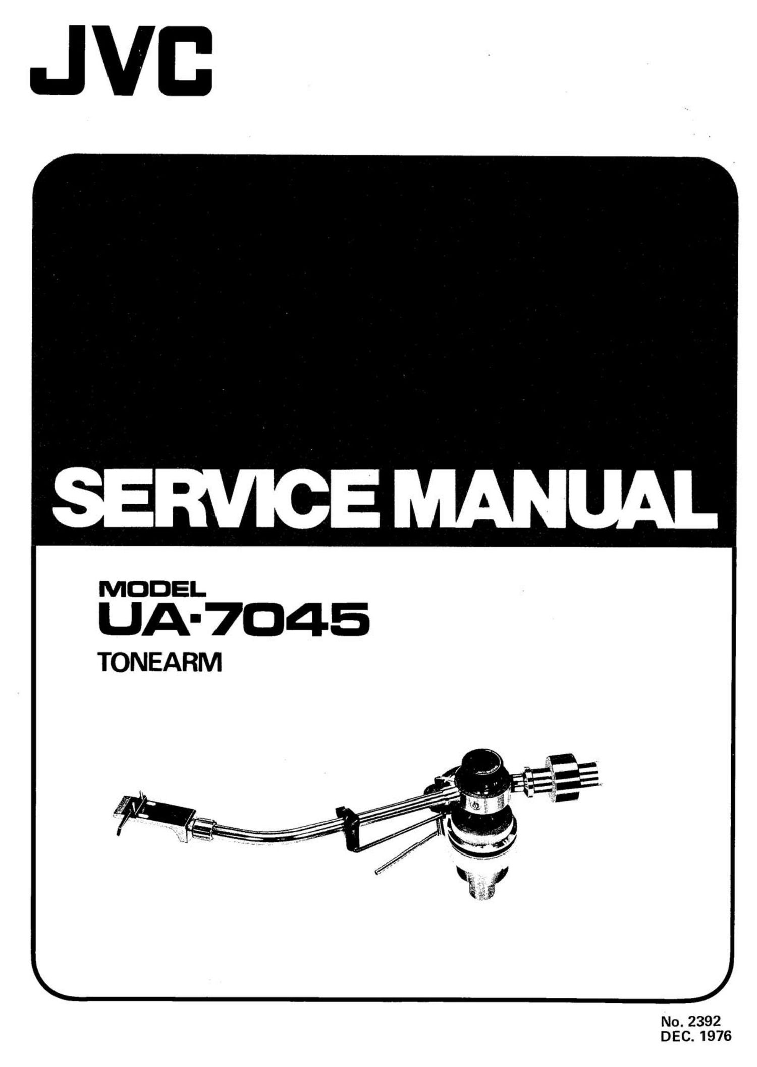
Jvc UA 7045 Service Manual

This is the 8 pages manual for Jvc UA 7045 Service Manual.
Read or download the pdf for free. If you want to contribute, please mail your pdfs to info@audioservicemanuals.com.

Page: 1 / 8
left right
Jvc UA 7045 Service Manual

Extracted text from Jvc UA 7045 Service Manual (Ocr-read)


Page 2

Contents 1 . Specifications

1. Specifications ......................... 1 Type: T.H. (Tracing-Hold) system, static balance, new
2. Features ............................. 1 gimbal support
3. Technical Comment on New Gimbal Support ..... 2 Overall length : 350mm
4. Names of Parts ......................... 2 Effective length : 245mm
5. Mounting, Setting-up and Adjustments Off~set angle : 21°40
5-(1) Tonearm mounting ................ 2 Tracking error : +1°48, -1°31'.
5-(2) Arm base mounting ................ 2 Overhang : 15mm
5-(3) Cartridge mounting ................ 2 Tracking force range : 0 - 39 (0.1g direct reading)
5-(4) Tonearm settingup ................ 3 Weight range (including shell) : 12 - 329
5-(5) Zero balance and tracking Height range : 40 - 60mm
force adjustment ................. 3 Weight : Approx. 6109
5(6) Anti-skating adjustment ........ ..... 3 Facilities: 1. Chucking lock head shell connector
5-(7) Head shell angle adjustment .......... 3 2. Helicoid type arm elevating system
5-(8) Overhang adjustment ............... 3 3. Forged head shell
5-(9) Arm rest ....................... 4 4. Oil-damped arm elevator
5-(10) Arm elevator assembly .............. 4 5. Anti-skating system
6. Main Dimensions ....................... 4 6. Low capacitance signal cords
7. Exploded View and Part Numbers ............ 5 D , _ . . . . _
8. Packing Materials and Accessories Part Numbers _ . . 6 esrgn and speCIfIcatIons sub/act to change Without notice.

2 . Features

. New gimbal support tonearm

The bearing system, utilizing high precision miniature
radial ball bearings positioned symmetrically, permits
the operational center of the bearings to be looked
upon as a single point. This new structure is achieved
with micron accuracy thanks to a new precision
machining technique. The advantages of both one-
point and gimbal support systems are combined in the
UA-7045; big sensitivity and excellent trackability on
the one hand and easy operability and outstanding
durability on the other hand.

. Chucking lock head shell connector

The head shell connector is double structured and the
inside cylinder is tapered expanding toward the out-
side. As you turn the plug-in nut to insert the head
shell, the inside cylinder sinks deeper into the con-
nector and the head shell becomes secured gradually
thanks to the cone~shape structure of the inside cylin-
der. The head shell connector thus permits the UA-
7045 to combine the high tone quality of integrated
type tonearms with the convenience of universal type
tonearms.

. Forged aluminum head shell

The head shell is forged from molten pure aluminum to
prevent blow holes, thus completing the resonance-free
design and ensuring excellent tone quality.

4. Tubular arm containing shock absorber

A light shock-absorbing material is packed inside the
tonearm to prevent resonance at a certain frequency.

UA-7045
No. 2392

10.

. Lift point

The lift point is provided to avoid unwanted horizontal
movement of the tonearm when descending and
ascending. Perpendicular movement is always assured.

Rotary type anti-skating knob

An easy-to-operate rotary type anti-skating knob is
provided on the upper side of the tonearm. Operation
feeling is exactly the same as that of the iris mechanism
on a camera, thus projecting that feeling of high pre-
cision.

Arm height fine adjustment

Arm height can be adjusted as smoothly as the zoom
lens of a camera, even while listening to a record, and a
height obtained which reduces the vertical tracking
error to a minimum.

. Arm rest with locking facility

Providing the arm rest with a dial type locking system
increases durability and minimizes the danger of
damage to the cartridge caused by accidental move-
ment of the tonearm.

Easy zero balancing and tracking force adjustment
Sliding the counterweight back and forth permits you
to coarse-adjust the zero balance. The fine adjustment
is then easily performed by merely turning the counter-
weight axis. Tracking force adjustment is quite easy.
Align the tracking force dial with the "0 mark, then
turn the weight shaft until you obtain the tracking
force you want.

Tubular arm of aluminum-magnesium-silicon alloy
Strength is three times that of conventional pure
aluminum arms. This greatly reduces resonance.