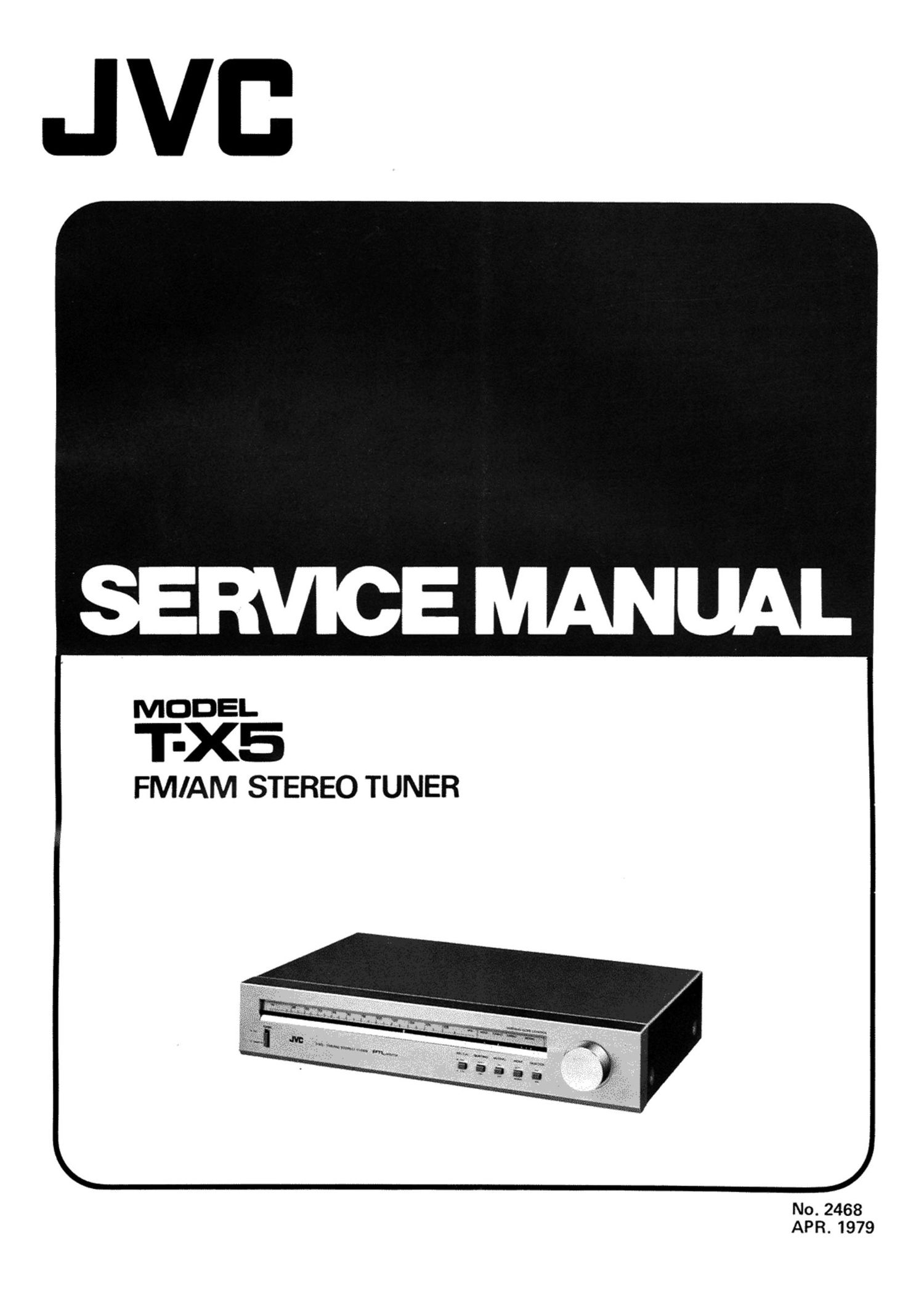
Jvc TX 5 Service Manual

This is the 21 pages manual for Jvc TX 5 Service Manual.
Read or download the pdf for free. If you want to contribute, please mail your pdfs to info@audioservicemanuals.com.

Page: 1 / 21
left right
Jvc TX 5 Service Manual

Extracted text from Jvc TX 5 Service Manual (Ocr-read)


Page 2

Contents

Page
1. Specifications .................................................................. 2
2. Explanation of New Technology
2-(1) Phase Tracking Loop (PTL) FM Discriminator ...................................... 2
2-(2) RF Stage Consisting Cascade-connected FETs in Parallel ............................... 4
2-(3) Quieting Slope Control Circuit ................................................ 4
2(4) Auto Tuning Hold Circuit ................................................... 5
3. Main Parts Location and Part Numbers .................................................. 6
4. Dial Stringing Procedures ........................................................... 6
5. Exploded Views and Removal Procedures ................................................ 7
6. FM/AM Tuner Alignment Procedures
6-(1) Frontend Section ......................................................... 8
6-(2) FM Section ............................................................. 8
6-(3) AM Section ............................................................. 8
7. Printed Circuit Board Assy and Parts List
7-(1) TXX-193B (or C) FM/AM Tuner and LED P.C. Board Ass'y ............................ 9
7-(2) TXX-194B (or C, D, E, FBS) Power Supply and Switches P.C. Board Ass'y .................. 13
8. Packing Materials and Part Numbers .................................................... 15
9. Accessories List ............. _ .................................................... 15
10. T-X5 Schematic Diagram ........................................................... 16
11. Parts List with Specified Numbers for Designated Areas ....................................... 18
This SET is switchable to the line voltage of 110, 120, 220 and
240 volts AC; 50/60 Hz.
The changeover switch is placed on the rear panel of the set.
To select another voltage, turn the changeover switch with a
screwdriver or coin.
But for the USA. and Canada, the set has no changeover switch,
and fixed only for the 120 volts AC; 50/60 Hz.
i Warning!
i W en replacing the parts marked with [l in the schematic diagram, be sure to use the designated parts to ensure safety. '
T-X5
No. 2468 _ 1 _