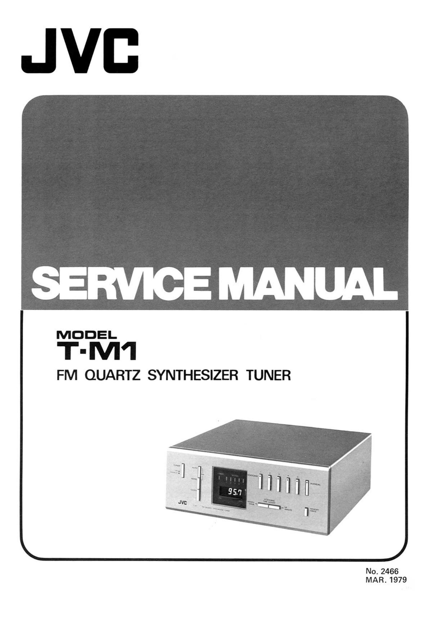
Jvc TM 1 Service Manual

This is the 20 pages manual for Jvc TM 1 Service Manual.
Read or download the pdf for free. If you want to contribute, please mail your pdfs to info@audioservicemanuals.com.

Page: 1 / 20
left right
Jvc TM 1 Service Manual

Extracted text from Jvc TM 1 Service Manual (Ocr-read)


Page 2

Contents

Page
1. Specifications ................................................................. 1
2 Names of Parts and Their Functions ................................................... 2
3 New Technology
3-(1) PLL Synthesizer ......................................................... 3
342) Presealer (uPBSS1C, IC 803) ................................................. 3
3-(3) PLL Synthesizer (uPDZ819C, IC 801) .......................................... 3
3-(4) Controller luPD1530C, IC 802) ............................................... 4
3-5) Segment Driver (X805 through X813) .......................................... 5
3-(6) Digit Driver (IC 804 and 805) ................................................ 5
3-0) Mode Select Circuits ...................................................... 6
3-(8) Preset Circuit ........................................................... 6
4. FM Alignment Procedures
441) Front End ............................................................. 5
4-l2) FM Section ............................................................ 5
443) Reference Signal Frequency ...................................... ' ........... 7
4-(4) Channel Separation ....................................................... 7
5. Removal Procedures
541) Metal Cover ................................ . ........................... 7
542) Front Panel ............................................................ 7
5(3) Tuner Board lTXX-1588) .................................................. 3
544) Synthesizer Board (TDC-35A) ................................................ 3
5-(5) Power Supply Board XX-160) .............................................. 8
546) Tuner Switch Board lTXX-160-2),
Mode Select Board (TXX-202-2).
Control Board (TXX-202A) .................................................. 8
5-(7) Digital Display Board (TOG-30) ............................................... 8
548) Station Indicator Board (TXX-202-3) ........................................... 8
6. Main Parts Locations ............................................................. 9
, 7. Exploded Views and Part Numbers
7-(1) Metal Cover ............................................................ 9
742) Front Panel & Chassis Base .................................................. 10
7-(3) Rear Panel 82 Chassis Base .................................................. 11
8. Printed Circuit Boards and Part Numbers
841) TXX-158 FM Tuner P.C. Board Assy 8i. TDC-30 Digital display P.C. Board Ass'y ............. 12
8-(2) TDC-35 Synthesizer P.C. Board Ass'y ......................................... 14
8-(3) TXX-160 Power Supply P.C. Board Ass'y ........................................ 16
8-(4) TXX-202 Mode Select and Control P.C. Board Assy ................................. 17
9. T-M1 Schematic Diagram .......................................................... 18
10. Packing Materials and Part Numbers ................................................... 20
11. Accessories List ................................................................ 20
12. Parts List with Specified Numbers for Designated Areas ...................................... 21
Warning: When replacing the parts marked with A , be sure to use the designated parts to ensure safety. !
1 , speCIflcatlons Antenna : 75 .Q unbalanced, 300 $2 balanced
Dimensions : 3 H 2 W
Tuning range : 87.5 MHz -- 108.0 MHZ {93-(11)/1x6"3)?(9-1)/)1(62'§3(:30-3T6")
Usable sensitivity : 0.9 pV/75 52 (10.3 dBf IHF) Weight : 3.7 kg (8 2 lbs)
50 dB S/N sensitivity : Mono 2.0 pV/75 9. (17.3 dBf IHF) Accessories : FM feeder antenna

Signal to noise ratio
(IH F A-network)

: Mono 75 dB

Stereo 72 dB Signal cord

Differences between Models intended for different areas.

Distortion at 1 kHz

: 0.08 % (Mono)

(100 % Mod.) 0.12 % (Stereo) gentinental U ed 0 h
- . urope, nit t er
Capture ratio ' 1'0 dB Australia Kingdom U.S.A. areas
Alternate channel Power supply 220-240 v» 240 V\, AC 120 v 110-120 w
selectIVlty : 75 dB 50 Hz so Hz 50/60 Hz 220-240 v
Image rejection : 75 dB selectable
- - 50/60 Hz
lF rejection : 90 dB Power
Spurious rejection : 90 dB consumption 12 w 12 w 11 w 12 w
AM suppression : 65 dB Line voltage
Stereo separation selector Fitted Nat fitted Net fitted Fitted
. Rear panel
at 1 kHz ' 50 dB power switch Not fitted . Fitted Not fitted Not fitted

Frequency response
Output level

No. 2466

:30 Hz- 15kHz+0.3dB,- 1.0dB
: 650 mV (400 Hz, 100 % Mod.)

Design and specifications subject to change without notice.

-1-

Page 4

3. New Technology
3-(1) PLL Synthesizer

Block diagram

XTAL
é.- REFERENCE F
L DIVIDER
MIXER ...
PHASE 5'
com-
id PARATOR
PRESCALER . Paige-gm- FD
"N DIVIDER
<5 A a
_| DATA meur
VARI. oc
DIODE
Fig. 2

Conventional radio receivers use variable capacitors
[or inductors) which are moved mechanically to tune to
broadcast signals. On the other hand PLL (Phase Lock
Loop) synthesizers vary the capacitance of a varactor
electronically to achieve the same object. in this system,
tuning is done by determining value N of the program-
mable divider, as shown above, by external digital signals.
In above figure, the closed loop (phase locked loop)
operates to equalize divided reference frequency Fr and
frequency FD which is the output frequency of the local
oscillator iVCO) prescaled to 1/Np by the prescaler and
further divided to UN by the programmable divider. In
fact, Fr is equal to FD when the phase locked loop
(PLL) is locked. Since

FD = Fvco/Np-N,

FVCO = Np-N-Fo = Np-N-Fr
Let Np = 20 and Fr = 5 kHz. Then,

FVCO=20xNx5kHz

= 100 x N kHz

Thus the VCO (local oscillator) frequency will vary in
intervals of 100 kHz as division ratio N of the pro-
grammable divider is varied in units of one. For FM
signals, the local oscillator frequency is as high as 98.2 to
118.7 MHz. In this case, a high-speed frequency divider
is used as the prescaler to reduce the input frequency of
the programmable divider.

K2302 X - 8313 LEO
W
SEGMENT 1 g
= DRIVER =3 bE' . S
I
Ill
1 5
5.76 mu_L- 7qu use .5. IT
a 25m 6' § ¢
T- PLL r. f common.
room meg, 5:5 KEV
svnruE» 0" 5 uAtmx
SIZER : Pu. can 4 _'
I. c: I
m.» 1
0C
, OIGI!
IO: 9 DRIVE
:gSCALE s» - I" - 5.93 Mu:

CV»:

F RON? END

VCO

F ' 98.2 - 113.7 NH]

T-M1

Fig. 3

No. 2466

3-(2) Prescaler (,uP8551 C. IC 803)

PRESCALER

C803
an
7
ICBO3 2 OP
uPBSSIC
Jr 4
-3 - G? _______________ J
Fig. 4

The local oscillator output (98.2 - 118.7 MHz) comes
from the front-end Four terminal (pin 15) to pin 2 of
uP3551C (IC 803, ECL) where the input frequency is
divided by 20 into FIN (4.91 - 5.935 MHz) and the re-
sulting signal is input to the programmable divider in
uP028190 (IC 801, PLL synthesizer).

WAVEFORM AT ® ,® , ©

@l/WWWWW 1w

W i

5V

Fig. 5

3-13) PLL Synthesizer
(#P02819C. IC 801)

TIME
BASE
25 Hz

CLOCK
360 kHz

5.76 MHz

LATCH ES

PROGRAMMABLE
DIVIDER

SHIFT REGISTER