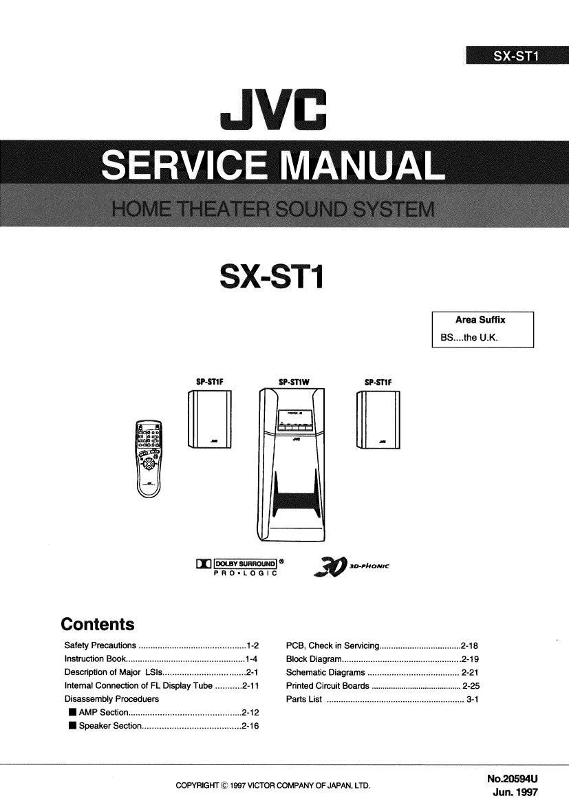
Jvc SXST 1 Service Manual

This is the 70 pages manual for Jvc SXST 1 Service Manual.
Read or download the pdf for free. If you want to contribute, please mail your pdfs to info@audioservicemanuals.com.

Page: 1 / 70
left right
Jvc SXST 1 Service Manual

Extracted text from Jvc SXST 1 Service Manual (Ocr-read)


Page 1

SX-ST1

JVI:
SERVICE MANUAL

SX-ST1


Area Suffix
BS....the U.K.
SP-STIF SP-SIIW SP~ST1F
\
I. M n
[13-o Home:
P a o - L o e I c
Contents
Safety Precautions ............................................. 1-2 PCB, Check in Semcing ................................... 2-18
lnstruciion Book ..................... 1-4 Block Diagram ............
Description of Major LSis ...... 2-1 Schematic Diagrams .
lntemal Connection of FL Display Tube ........... 2-11 Printed Circuit Boards
Disassembly Prooeduers Parts List
I AMP Section ........

I Speaker Section .....

No.20594U

COPYRIGHT © 1997 VICTOR COMPANY OF JAPAN. LTD.
Jun. 1997

Page 2

- Safety Precautions

1.

SX-ST1 mj

The design of this product contains special hardware and many circuits and components
specially for safety purposes. For continued protection, no changes should be made to the
original design unless authorised in writing by the manufacturer. Replacement parts must
be identical to those used in the original circuits.

.Any unauthorised design alterations or additions will void the manufacturers guarantee;

furthermore the manufacturer cannot accept responsibility for personal injury or property
damage resulting therefrom.

. Essential safety critical components are identified by (A) on the Parts List and by shading

on the schematic .and must never be replaced by parts other than those listed in the
manual. Please note however that many electrical and mechanical parts in the product have
special safety related characteristic. These characteristic are often not evident from visual
inspection. Parts other than specified by the manufacturer may not have the same safety
characteristic as the recommended replacement parts shown in the Parts List of the service
manual and may create shock,fire,or other hazards.

. The leads in the products are routed and dressed with ties, clamps, tubings, barriers and

the like to be separated from live parts, high temperature parts, moving parts and/or sharp
edges for the prevention of electric shock and fire hazard. When service is required, the
original lead routing and dress should be observed, and it should be confirmed that they
have been returned to normal, after re-assembling.

1.

Warning

Service should be performed by qualified personnel only.

2.This equipment has been designed and manufactured to meet international safety standards.

3.

It is the legal responsibility of the repairer to ensure that these safety standards are
maintained.

4. Repairs must be made in accordance with the relevant safety standards.
5. It is essential that safety critical components are replaced by approved parts.
6. If mains voltage selector is provided, check setting for local voltage.