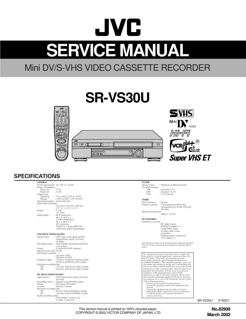
Jvc SRVS 30 U Service Manual

This is the 136 pages manual for Jvc SRVS 30 U Service Manual.
Read or download the pdf for free. If you want to contribute, please mail your pdfs to info@audioservicemanuals.com.

Page: 1 / 136
left right
Jvc SRVS 30 U Service Manual

Extracted text from Jvc SRVS 30 U Service Manual (Ocr-read)


Page 1

Page 2

TABLE OF CONTENTS Section Title Page Section Title Page Important Safety Precautions INSTRUCTIONS 1. DISASSEMBLY 1.1 HOW TO REMOVE THE MAJOR PARTS ........................................ 1-1 1.1.1 Introduction ........................................................................\ .......... 1-1 1.2 HOW TO READ THE DISASSEMBLY AND ASSEMBLY .................. 1-1 1.3 DISCONNECTION OF CONNECTORS (WIRES) ............................ 1-1 1.4 HOW TO REMOVE THE MAJOR PARTS .............. 1-2 1.4.1 Disassembly flow chart ................................................................ 1-2 1.4.2 Disassembly/assembly method ......................... 1-2 1.5 HOW TO REMOVE THE MAJOR PARTS ............... 1-4 1.5.1 Disassembly flow chart ................................................................ 1-4 1.5.2 DIsassembly/assembly method .......................... 1-4 1.6 HOW TO REMOVE THE MAJOR PARTS .................. 1-6 1.6.1 Disassembly flow chart ................................................................ 1-6 1.6.2 Disassembly/assembly method ............................. 1-6 1.7 CONNECTION ........................................................................\ .......... 1-8 1.8 SERVICE POSITIONS .................................................................... 1-10 1.8.1 Requirement PATCH CORDS .................................................... 1-10 1.8.2 Service position .................................................... 1-10 1.8.3 Service position ............................................. 1-10 1.8.4 Service position .............................. 1-11 1.9 Jig RCU mode ........................................................................\ ......... 1-11 1.9.1 Setting the Jig RCU mode ......................................................... 1-11 1.9.2 Setting the User RCU mode ...................................................... 1-11 1.10 MECHANISM SERVICE MODE ................................................... 1-12 1.10.1 How to set the ÒMECHANISM SERVICE MODEÓ .................... 1-12 1.11 EMERGENCY DISPLAY FUNCTION ............................................ 1-13 1.11.1 Displaying the emergency information ..................................... 1-13 1.11.2 Clearing the emergency history ............................................... 1-13 1.11.3 Emergency content description ................................................ 1-14 1.11.4 Emergency detail information <1> ........................................... 1-15 1.11.5 Emergency detail information <2> ........................................... 1-16 2. MECHANISM ADJUSTMENT (VHS) 2.1 BEFORE STARTING REPAIR AND ADJUSTMENT ......................... 2-1 2.1.1 Precautions ........................................................................\ .......... 2-1 2.1.2 Checking for Proper Mechanical Operations ............................... 2-1 2.1.3 Manually Removing the Cassette Tape ....................................... 2-1 2.1.4 Jigs and Tools Required for Adjustment ....................................... 2-2 2.1.5 Maintenance and Inspection ........................................................ 2-3 2.2 REPLACEMENT OF MAJOR PARTS ............................................... 2-6 2.2.1 Before Starting Disassembling(Phase matching between mechanical parts) ............................... 2-6 2.2.2 How to Set the Mechanism Assembling Mode ............................. 2-6 2.2.3 Cassette Holder Assembly ........................................................... 2-6 2.2.4 Pinch Roller Arm Assembly .......................................................... 2-8 2.2.5 Guide Arm Assembly and Press Lever Assembly ........................ 2-8 2.2.6 Audio Control Head ...................................................................... 2-8 2.2.7 Loading Motor ........................................................................\ ...... 2-8 2.2.8 Capstan Motor ........................................................................\ ..... 2-9 2.2.9 Pole Base Assembly (supply or take-up side) .............................. 2-9 2.2.10 Rotary Encoder ........................................................................\ 2-10 2.2.11 Clutch Unit ........................................................................\ ........ 2-10 2.2.12 Change Lever Assembly, Direct Gear, Clutch Gear and Coupling Gear .................................................................... 2-10 2.2.13 Link Lever ........................................................................\ ........ 2-11 2.2.14 Cassette Gear, Control Cam and Worm Gear ......................... 2-11 2.2.15 Control Plate ........................................................................\ .... 2-11 2.2.16 Loading Arm Gear (supply or take-up side) and Loading Arm Gear Shaft .................................................... 2-12 2.2.17 Take-up Lever, Take-up Head and Control Plate Guide .................. 2-13 2.2.18 Capstan Brake Assembly ......................................................... 2-13 2.2.19 Sub Brake Assembly (take-up side) ......................................... 2-13 2.2.20 Main Brake Assembly (take-up side), Reel Disk (take-up side) and Main Brake Assembly (supply side) ................................... 2-13 2.2.21 Tension Brake Assembly, Reel Disk (supply side) and Tension Arm Assembly ....................................................... 2-14 2.2.22 Idler Lever, Idler Arm Assembly ............................................... 2-14 2.2.23 Stator Assembly ....................................................................... 2-14 2.2.24 Rotor Assembly ........................................................................\ 2-14 2.2.25 Upper Drum Assembly ............................................................. 2-15 2.3 COMPATIBILITY ADJUSTMENT .................................................. 2-16 2.3.1 Checking/Adjustment of FM Waveform Linearity ....................... 2-16 2.3.2 Checking/Adjustment of the Height and Tilt of the Audio Control Head .................... 2-17 2.3.3 Checking/Adjustment of the Audio Control Head Phase (X-Value) ............... 2-17 2.3.4 Checking/Adjustment of the Standard Tracking Preset ............. 2-18 2.3.5 Checking/Adjustment of the Tension Pole Position .................... 2-18 MECHANISM ADJUSTMENT (DV) 2.4 PREPARATION ........................................................................\ ....... 2-20 2.4.1 Precautions ........................................................................\ ........ 2-20 2.4.2 Tools Required for Adjustments ................................................. 2-20 2.4.3 Disassembly and Assembly Procedures .................................... 2-20 2.4.4 Screws and Washers Used in Disassembly/ Assembly of the Mechanism Assembly ...................................... 2-20 2.5 DISASSEMBLY/ASSEMBLY OF THE MECHANISM ASSEMBLY ................... 2-21 2.5.1 Introduction ........................................................................\ ........ 2-21 2.5.2 Mechanism Modes ..................................................................... 2-21 2.6 MECHANISM TIMING CHART ....................................................... 2-23 2.7 MECHANISM ASSEMBLY/DISASSEMBLY PROCEDURE TABLE .................. 2-24 2.8 DISASSEMBLY/ASSEMBLY ........................................................... 2-26 2.9 LIST OF PROCEDURES FOR DISASSEMBLY ............................. 2-34 2.10 MECHANISM PHASE CHECK/ADJUSTMENT ............................ 2-35 2.11 MECHANISM DISASSEMBLY/ASSEMBLY SHEET ..................... 2-36 2.12 POSITIONING THE TENSION POLE ........................................... 2-38 2.13 COMPATIBILITY AND ERROR RATE ADJUSTMENTS ................. 2-39 2.13.1 Preparation ........................................................................\ ...... 2-39 2.13.2 Adjustment ........................................................................\ ....... 2-39 2.13.3 Linearity adjustment ................................................................. 2-40 2.13.4 PB switching point adjustment ................................................. 2-40 2.13.5 Error rate adjustment ............................................................... 2-40 2.13.6 Error rate measuring method ................................................... 2-40 2.14 TAPE EJECTION ........................................................................\ .. 2-41 3. ELECTRICAL ADJUSTMENT (VHS) 3.1 PRECAUTION ........................................................................\ .......... 3-1 3.1.1 Required test equipments ............................................................ 3-1 3.1.2 Required adjustment tools ........................................................... 3-1 3.1.3 Color (colour) bar signal,Color (colour) bar pattern ..................... 3-1 3.1.4 Switch settings and standard precautions ................................... 3-1 3.1.5 EVR Adjustment ........................................................................\ ... 3-1 3.2 SERVO CIRCUIT ........................................................................\ ...... 3-2 3.2.1 Switching point ........................................................................\ ..... 3-2 3.2.2 Slow tracking preset ..................................................................... 3-2 3.3 VIDEO CIRCUIT ........................................................................\ ....... 3-2 3.3.1 D/A level ........................................................................\ ............... 3-2 3.3.2 EE Y/PB Y (S-VHS/VHS) level ..................................................... 3-2 3.3.3 REC color (colour) level ............................................................... 3-3 3.3.5 Video EQ (Frequency response) ................................................. 3-3 3.3.6 AUTO PICTURE initial setting ...................................................... 3-4 3.3.6 DV EE Y level ........................................................................\ ....... 3-4 3.4 AUDIO CIRCUIT ........................................................................\ ....... 3-4 3.4.1 Audio REC FM ........................................................................\ ..... 3-4 3.5 DEMODULATOR CIRCUIT ............................................................... 3-5 3.5.1 Input level ........................................................................\ ............. 3-5 3.5.2 Stereo VCO ........................................................................\ .......... 3-5 3.5.3 Stereo filter ........................................................................\ ........... 3-5 3.5.4 Separation-1 ........................................................................\ ........ 3-5 3.5.5 Separation-2 ........................................................................\ ........ 3-6 3.5.6 SAP VCO ........................................................................\ ............. 3-6 ELECTRICAL ADJUSTMENT (DV) 3.6 PREPARATION ........................................................................\ ......... 3-7 3.6.1 Precautions ........................................................................\ .......... 3-7 3.6.2 Equipment required for adjustment .............................................. 3-7 3.6.3 Tools required for adjustments ..................................................... 3-7 3.6.4 Setup ........................................................................\ .................... 3-7 4. CHARTS AND DIAGRAMS NOTES OF SCHEMATIC DIAGRAM ..................................................... 4-1 CIRCUIT BOARD NOTES ...................................................................... 4-2 4.1 BOARD INTERCONNECTIONS ....................................................... 4-3 4.2 SWITCHING REGULATOR SCHEMATIC DIAGRAM[HR-DVS3U/SR-VS30U] .. 4-5 4.3 MAIN (VIDEO/AUDIO) SCHEMATIC DIAGRAM .............................. 4-7 4.4 MAIN (VHS SYSCON) SCHEMATIC DIAGRAM .............................. 4-9 4.5 MAIN (TUNER) SCHEMATIC DIAGRAM ....................................... 4-11 4.6 MAIN (VIDEO I/O & SUB EMPHA) SCHEMATIC DIAGRAM ......... 4-13 4.7 MAIN (AUDIO I/O) SCHEMATIC DIAGRAM ................................... 4-15 4.8 MAIN (CONNECTION) SCHEMATIC DIAGRAM ............................ 4-17 4.9 3D DIGITAL/2M SCHEMATIC DIAGRAM ....................................... 4-19 4.10 TERMINAL (S-SUB) SCHEMATIC DIAGRAM .............................. 4-21 4.11 TERMINAL (I/O) SCHEMATIC DIAGRAM .................................... 4-23 4.12 DEMODULATOR SCHEMATIC DIAGRAM[HR-DVS3U/SR-VS30U] .. 4-25 4.13 POWER SW, SW/DISPLAY AND JOG SCHEMATIC DIAGRAMS .... 4-27 4.14 DV MSD SCHEMATIC DIAGRAM ................................................ 4-29 4.15 DV MAIN SCHEMATIC DIAGRAM ............................................... 4-31 4.16 DV I/O SCHEMATIC DIAGRAM ................................................... 4-33 4.17 DV V OUT SCHEMATIC DIAGRAM ............................................. 4-35 4.18 DV PRE/REC SCHEMATIC DIAGRAM ........................................ 4-37 4.19 DV REG SCHEMATIC DIAGRAM ................................................ 4-38 4.20 DV AUDIO AD/DA SCHEMATIC DIAGRAM ................................. 4-39 4.21 MAIN(ON SCREEN) SCHEMATIC DIAGRAM ............................. 4-40 4.22 SWITCHING REGULATOR CIRCUIT BOARD ............................. 4-41 4.23 MAIN CIRCUIT BOARD ................................................................ 4-43 4.24 3D DIGITAL/2M CIRCUIT BOARD ............................................... 4-46 4.25 DEMODULATOR, POWER SW, SW/DISPLAY AND JOG CIRCUIT BOARDS .... 4-47 4.26 TERMINAL CIRCUIT BOARD ....................................................... 4-49 4.27 DV MAIN CIRCUIT BOARD .......................................................... 4-51 4.28 REMOTE CONTROL SCHEMATIC DIAGRAM ............................ 4-53 4.29 WAVEFORMS ........................................................................\ ....... 4-54 4.30 VOLTAGE CHARTS ...................................................................... 4-55 4.31 FDP GRID ASSIGNMENT AND ANODE CONNECTION ............. 4-57 4.32 CPU PIN FUNCTION .................................................................... 4-58 4.33 SYSTEM CONTROL BLOCK DIAGRAM (VHS) ........................... 4-59 4.34 VIDEO BLOCK DIAGRAM(VHS) .................................................. 4-61 4.35 AUDIO BLOCK DIAGRAM (VHS) ................................................. 4-65 4.36 SYSTEM CONTROL BLOCK DIAGRAM (DV) ............................. 4-67 4.37 VIDEO BLOCK DIAGRAM (DV) ................................................... 4-69 5. PARTS LIST 5.1 PACKING AND ACCESSORY ASSEMBLY ............................ 5-1 5.2 FINAL ASSEMBLY .................................................................. 5-2 5.3 MECHANISM ASSEMBLY (VHS) ........................................... 5-4 5.4 MECHANISM ASSEMBLY (DV) .............................................. 5-6 5.5 ELECTRICAL PARTS LIST ............................................................... 5-8 SW REGULATOR BOARD ASSEMBLY <01> ........................................ 5-8 MAIN BOARD ASSEMBLY <03> ............................................................ 5-9 3D DIGITAL/2M BOARD ASSEMBLY <05> .......................................... 5-17 TERMINAL BOARD ASSEMBLY <06> ................................................. 5-18 A/C HEAD BOARD ASSEMBLY <12> .................................................. 5-19 DEMOD BOARD ASSEMBLY <14> ...................................................... 5-19 POWER BOARD ASSEMBLY <27> ...................................................... 5-19 SW/DISPLAY BOARD ASSEMBLY <28> ............................................. 5-19 DV MAIN BOARD ASSEMBLY <50> .................................................... 5-20 LOADING MOTOR BOARD ASSEMBLY <55> ..................................... 5-25 JOG BOARD ASSEMBLY <85> ............................................................ 5-25

Page 26

2-5 Symbols and numbers Symbols and numbers Number of removal steps Guide rail Roller cam assembly Cassette housing bracket Opener guide Relay gear Cassette holder assembly Drive gear Drive arm Pinch roller arm assembly Guide arm assembly Press lever assembly UV catcher2 Rotary encoder Clutch unit Change lever assembly Direct gear Coupling gear Link lever Worm gear Control bracket1 Control plate Loading arm gear (supply side) Loading arm gear (take-up side) Take-up lever Sub brake assembly (take-up side) Main brake assembly (take-up side) Reel disk (take-up side) Tension brake assembly Tension arm assembly Idler lever Brake lever (*1) Front (T)/Back (B) of mechanism (Reference items) Replacement partsRemoval parts L1 L1 L2 L2 R4 R1 R2 R5 R3 T9 T12 T11 T6 T7 B1 T1 T17 T10 T14 T15 T19 T13 T22 T20 T24 B9 T18 T16 B19 B16 B7 B8 B5 B4 B3 B11 B10 T25 B15 B12 B14 B13 B17 B18 B20 B21 R4 R1 R3 T9 T12 T11 B15 B12 B14 B13 B17 B21 B7 B8 B5 B4 B11 T14 T15 T13 T22 T24 T18 B19 T1 2.2.3 Guide rail T 1 2.2.3 Roller cam assembly T 1 2.2.3 Cassette housing bracket T 1 2.2.3 Opener guide T 2 2.2.3 Door opener T 3 2.2.3 Relay gear T 3 2.2.3 Limit gear T 3 2.2.3 Cassette holder assembly T 6 2.2.3 Drive gear T 4 2.2.3 Drive arm T 8 2.2.4 Pinch roller arm assembly T 1 2.2.5 Guide arm assembly T 1 2.2.5 Press lever assembly T 3 2.2.6 A/C head T 1 2.2.7 Loading motor T 1 2.2.8 Capstan motor T/B 1 2.2.9 UV catcher2 T 1 2.2.9 Pole base assembly (take-up side) T/B 2 2.2.9 Pole base assembly (supply side) T/B 2 2.2.10 Rotary encoder B 1 2.2.11 Clutch unit B 1 2.2.12 Change lever assembly B 3 2.2.12 Direct gear B 4 2.2.12 Coupling gear B 5 2.2.12 Clutch gear B 6 2.2.13 Link lever B 1 2.2.14 Cassette gear B 2 2.2.14 Control cam B 2 2.2.14 Worm gear B 1 - Lid guide T/B 5 2.2.15 Control bracket1 B 1 2.2.15 Control plate B 6 2.2.16 Loading arm gear (supply side) B 7 2.2.16 Loading arm gear (take-up side) B8 2.2.16 Loading arm gear shaft B 9 2.2.17 Take-up lever T/B 7 2.2.17 Take-up head T/B 8 2.2.17 Control plate guide T/B 8 2.2.18 Capstan brake assembly T/B 7 2.2.19 Sub brake assembly(take-up side) T/B 15 2.2.20 Main brake assembly(take-up side) T/B 16 2.2.20 Main brake assembly(supply side) T/B 9 2.2.20 Reel disk (take-up side) T/B 16 2.2.21 Tension brake assembly T/B 9 2.2.21 Reel disk (supply side) T/B 10 2.2.21 Tension arm assembly T/B 10 2.2.21 Tension arm bearing T/B 10 2.2.22 Idler lever T/B 17 2.2.22 Idler arm assembly T/B 18 - Brake lever ( *1) T/B 18 - Rotary encoder guide T/B 19 1 2 3 4 5 6 7 8 9 10 11 12 13 14 15 16 17 18 1 2 3 4 5 6 7 8 9 10 11 12 13 14 15 16 17 1 2 3 4 5 6 7 8 9 10 11 12 13 14 15 16 17 1 2 3 4 5 6 7 8 9 10 11 12 13 14 15 16 1 2 3 4 5 6 7 8 9 1 2 3 4 5 6 7 8 9 1 2 3 4 5 6 7 8 9 1 2 3 4 5 6 7 8 1 2 3 4 5 6 7 8 9 10 11 12 13 14 15 1 2 3 4 5 6 7 8 1 2 3 4 5 6 7 8 9 10 11 12 13 14 15 1 2 3 4 12 12 3 12 1 1 1 2 3 4 1 2 3 4 5 5 6 1 2 3 4 5 6 1 2 3 4 5 6 7 12 12 12 1 1 2 3 12 3 4 5 1 2 3 4 5 6 7 7 1 2 3 4 5 6 1 2 3 4 5 6 1 2 3 4 5 6 7 1 2 3 4 5 6 1 2 3 4 5 1 2 3 4 1 1 1 2 3 4 5 6 7 8 7 8 9 10 11 12 13 14 Table 2-1-5b Note: ¥ The parts with marked ( * ) have different types of mecha- nisms (standard type or high-speed FF/REW type). *1 : Uses the standard type mechanism only. *2 : Uses the high-speed FF/REW type mechanism only.

Page 65

3-3 Fig. 3-3-2a EE/PB Y level H. rate Y level (1) Connect the adjustment tool (H2) to the measuring point (D1). (2) Apply the external trigger signal to D.FF (E) to observe the PB color (colour) waveform at the measuring point (D2). (3) Play back the signal (A3) in the mode (B1) of the align-ment tape (A1). (4) Set the VCR to the manual tracking mode. (5) Adjust tracking so that the PB color (colour) waveform becomes maximum. Make a note of the higher PB color (colour) level as ÒBÓ at this time. (6) Record the signal (A3) in the mode (B1), and play back the recorded signal. (7) Set the VCR to the EVR mode by transmitting the code (F1) from the Jig RCU. (8) Set the EVR address to (F2) by transmitting the code (F3) from the Jig RCU. (9) Transmit the code (F4) from the Jig RCU to adjust so that the higher level channel becomes the specified value (G) of the note "B" level as shown in Fig. 3-3-3b. (Adjust be- fore recording, then confirm it by playing back.) (10) After adjustment, record the signal (A3) then playing it back again. At this time, confirm that there is no invert- ing phenomenon or noise appearing on the playback screen. Fig. 3-3-3a LPF 1 k¯ 39 µH 180 µH 120 pF 180 pF PB. FM 629 [kHz] PB COLOR (PB COLOUR) 3.3.3 REC color (colour) level Signal (A1) ¥Alignment tape(S-VHS, SP/EP, Color(colour) bar) [MH-1H] (A2) ¥Ext. input (A3) ¥Color (colour) bar signal [NTSC] Mode (B1) ¥S-VHS SP (B2) ¥S-VHS EP Equipment (C) ¥Oscilloscope Measuring point (D1) ¥TP106 (PB. FM) (D2) ¥PB color (colour) output of the LPF External trigger (E) ¥TP111 (D.FF) EVR mode (F1) ¥Jig code Ò57Ó EVR address (F2)¥A : 02 (F3)¥Jig code Ò20Ó and Ò22Ó (F4) ¥Jig code Ò18Ó or Ò19Ó (Channel +/-) Specified value (G) ¥SP: ÒBÓ x 125 ± 5%¥EP: ÒBÓ x 125 ± 5% Adjustment tool (H1) ¥Jig RCU [PTU94023B] (H2) ¥ LPF [PTU93006] (See Fig. 3-3-3a.) Note: ¥ After adjusting, always perform the confirmation and re-adjustment of the item 3.4.1. Fig. 3-3-3b REC color (colour) level V. rate Specified value (G) (11) Release the EVR mode of the VCR by transmitting the code (F1) from the Jig RCU again. (When the EVR mode is released, the adjusted data is memorized.) (12) Repeat steps (3) to (11) in the mode (B2). 3.3.4 Video EQ (Frequency response) Signal (A1) ¥Ext. S-input (A2) ¥Video sweep signal Mode (B1) ¥S-VHS SP (B2)¥S-VHS EP (B3)¥Picture Control / Smart Picture REC : Normal / Natural PB : Edit / Distinct Equipment (C) ¥Oscilloscope Measuring point (D1) ¥Y OUT terminal (75 ¯ terminated) Frequency marker(D2) ¥3 [MHz] External trigger (E) ¥TP111 (D.FF) EVR mode (F1) ¥Jig code Ò57Ó EVR address (F2)¥A : 03 (F3)¥Jig code Ò20Ó and Ò23Ó (F4) ¥Jig code Ò18Ó or Ò19Ó (Channel +/-) Specified value (G) ¥SP: 2.8 ± 0.3 div. (Ð3 ± 1 dB)¥EP: 2.8 ± 0.3 div. (Ð3 ± 1 dB) Adjustment tool (H) ¥Jig RCU [PTU94023B] (1) Apply the external trigger signal to D.FF (E) to observe the Y OUT waveform at the measuring point (D1). (2) Record the signal (A2) in the mode (B1), and play back the recorded signal. (3) Set the VCR to the manual tracking mode. (4) Set the VCR to the EVR mode by transmitting the code (F1) from the Jig RCU. (5) Set the EVR address to (F2) by transmitting the code (F3) from the Jig RCU. (6) Set the slope of the oscilloscope to the channel having higher (D2) marker level of the Y OUT waveform [signal (A2)]. Then set the 100 kHz marker level to the Ò4Ó scale on the oscilloscope. In this condition, transmit the code (F4) from the Jig RCU to adjust so that the (D2) marker level reaches the specified value (G). (7) Release the EVR mode of the VCR by transmitting the code (F1) from the Jig RCU again. (When the EVR mode is released, the adjusted data is memorized.) (8) Repeat steps (2) to (7) in the mode (B2). (7) Record the signal (A2) in the mode (B2), and play back the recorded signal. (8) Set the VCR to the manual tracking mode. (9) Repeat steps (1) to (5) in the mode (B2). (10 ) Record the signal (A2) in the mode (B3), and play back the recorded signal. (11 ) Set the VCR to the manual tracking mode. (12 ) Repeat steps (1) to (5) in the mode (B3). 100 kHz Four scale 1 MHz 2 MHz Frequency marker (D2) Specified value (G) 5 MHz V. rate Scale 4 (4 div.) Fig. 3-3-4a Video EQ (Frequency Response)