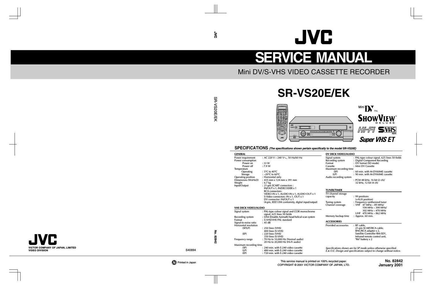
Jvc SRVS 20 E Schematic

This is the 149 pages manual for Jvc SRVS 20 E Schematic.
Read or download the pdf for free. If you want to contribute, please mail your pdfs to info@audioservicemanuals.com.

Page: 1 / 149
left right
Jvc SRVS 20 E Schematic

Extracted text from Jvc SRVS 20 E Schematic (Ocr-read)


Page 2

Secfion Tflb

Important Safety Precautions
INSTRUCTIONS
1. DISASSEMBLV

1.1 HOW TO REMOVE THE MAJOR PARTS
1.1.1 Introduction

1.2 HOW TO READ THE DISASSEMBLY AND ASSEMBLY

1.3 DISCONNECTION OF CONNECTORS WIRES) ..
1.
1.
Disassembly Ilow chart
Disassembly/assembly method
1
1 Disassembly Ilow chart
2 Disassembl lassembl method .
1 HOW TO REMO E THE
.1 Disassembly Ilow chart

.2 Disassembly/assembly method .
SERVICE POSITIONS

4
5

1.5
1.5
1.6
1.6
1.7
1.7
1.8.1 Service position 1.
1.
1

1

1.
1.
1.
1.
1.

6
7
B

1

.2 Service osition
MECHANI M SERVICE MODE
9.1 How to set the "MECHANIS
0 CONNECTION
1 EMERGENCY DIS

1.9
11.1 Displaying the emergency informa
11.2 Clearing the emergency history
11.3 Emergency content description
11.4 Emergency detail inlormation
11.5 Emergency detail inlormation ,

2. MECHANISM ADJUSTMENT (VHS)
2.1 BEFORE STARTING REPAIRANDADJUSTMENT
.1 Precautions

3 Manualhv Removing the Cassette Tape .
.4 Jigs an Tools Required IorAdjustment.
.5 Maintenance and Ins ection .
REPLACEMENT OF M OR PARTS.
.1

2

mechanical pans)
2 2 How to Set the Mechanism Assembling Mode.

2 3 Cassette Holder Assembly

2 4 Pinch RollerArm Assembly"

2.5 Guide Ann Assembly and ress LeverAssembly
.26 Audio Control Head.
2.7 Loading Motor
2 8 Ca stan Moto
2 9 Po e Base Assembly (supply or take-up side
2 1 Rotary Encode
21 Clutch Unit ..

2 1

Link ever
Cassette G
Control Plate
Loading Arm 6

Cagstan Brake Assembly

Su Brake Assembly (ta e p
Main Brake Assembly (take-up side), ee
and Main Brake Assembly (supply side) .....

Tension Arm Assembly
Idler Lever, Idler Arm Assembly .
Stator Assembly .
Rotor Assembly .
Upper Drum Assembly.
COMPATIBILITY ADJUSTMENT .
Checking/Adjustment of FM Waveform Lineanty

Checking/A
CHANISM ADJUSTMENT (DV)
PREPARATION .
Precautions

SCREWS USED CABINET COMPONENT AND BOARD ASSEMBLIES
HOW TO REMOVE THE MAJOR PARTS

HOW TO REMOVE THE MAJOR PARTS

AJOR PARTS

Before Starting Disassembling (Phase matching between


Change Lever Assembly Direct Gear Clutch Gear and Coupling Gea
DD V P g
Take-up Lever, lsake-up Head and Control Plate Guide .

Tension Brake Assembly, Reel Disk (supply si e) an

. .1

. .2 Checking/Ad'ustment oi the Height and Tilt ol the Audio Control Head
. .3 Checking/A justment of the Audio Control Head Phase (X-Value)
. .4 Checking/Agjustment of the Standard Tracking Preset .
. .5 justment of the Tension Pole Position .

TABLE OF CONTENTS

Page

mmmmm-b-b-bNNN-AAAA

mmmrpmmm

"""....."°NNN


mmmmmmmmmmr}: N NNNNNNNNNN' ' ' - - - - -
mmflflmmmbbbb w wwwNA-Aooommmmmmmma mum-i444

9.1
9.2 Tools Requir ]
9.3 Disassembly and Assembly Pro
9.4 Screws and Washers Used in Disassem y ssem y o
Mechanism Assembly
2.10 DISASSEMBLY/ASSEMBLY
2.10.1 Introduction
2.10.2 Mechanism Modes
2.11 MECHANISM TIMING CHART 2-24
2.12 MECHANISM ASSEMBLY/DISASSEMBLY PROCEDURE TABLE 2-25
2.13 DISASSEMBLY/ASSEMBLY 2-27
2.14 LIST OF PROCEDURES FOR DISASSEMBLY . 2-35
2.15 MECHANISM DISASSEMBLY/ASSEMBLY SHEET. 2-36
2.16 MECHANISM PHASE CHECK/ADJUSTMENT 2-38
2.17 POSITIONING THE TENSION POLE 2-39
2.18 COMPATIBILITY AND ERROR RATE ADJUSTMENTS 2-40
2.18.1 Preparation . 2-40
2.18.2 Adjustmen 2-40
2.18.3 Lineari adjustment . 2-41
2.18.4 PB switching point adjustment 2-41
2.18.5 Error rate adjustment 2-41
2.18.6 Error rate measuring method. 2-41
2.19 TAPE EJECTION

Secfion THE

3. ELECTRICAL ADJUSTMENT (VHS)
3.1 PRECAUTION ..
Required tes q p
2 Required adjustment tool

3 Colcr(cclour) bar signal,Co or (co our) ar pa ern
Switch settings and standard precautions
5 EVR Adjustment
1

2

1

Page


.1.
.1.
.1.
.1

.1.

w

SERVO CIRCUIT.

Switching pom

Slow tracking preset
VIDEO CIRCU T

w

. D/A level .
.2 EE Y level
.3 PB Y level (S-VHS / VHS) .
.g REC color colour) level .
.6
.7

Video EC ( requency response) .
AUTO PICTURE initial setting .
DV EE Y level
AUDIO CIRCUIT
1 Audio REC FM

YSCON CIRCUIT [SR-VSZOE]
.1 Timerclock

E ECTRICAL ADJUSTMENT (DV)
3.6 PREPARATION.
3.6.1 Precautions
3.6.2 Equipment required for adjustment.
3.6.3 Tools required Ior adjustments .
3.6.4 Setup...

4. CHARTS AND DIAGRAMS
NOTES OF SCHEMATIC DIAGRAM
CIRCUIT BOARD NOTES ..
4 1 BOARD INTERCONNECTIONS
SWITCHING REGULATOR AND REGULATOR SCHEMATIC DIAGRAMS .
VIDEO/AUDIO SCHEMATIC DIAGRAM
SYSTEM CONTROL SCHEMATIC DIAG
SUB CPU SCHEMATIC DIAGRAM
TUNER SCHEMATIC DIAGRAM .
VIDEO IIO SWITCH SCHEMATIC
AUDIO l/O SCHEMATIC DIAGRAM
CONNECTION SCHEMATIC DIAGRA
3D DIGITAL/2M SCHEMATIC DIAGRA
TERMINAL SCHEMATIC DIAGRAM
DEMODULATOR SCHEMATIC DIAGR
S-SUB SCHEMATIC DIAGRAM
MDA SCHEMATIC DIAGRAM
PRE/REC SCHEMATIC DIAGRA
ON SCREEN SCHEMATIC DIAGRAM
DISPLAY, EJECT SW, LED/SW. JACK AND JOG SCHEMATIC DIAGRAMS
DV SYSTEM CONTROL SCHEMATIC DIAGRAM
DV MSD SCHEMATIC DIAGRAM
DV MAIN SCHEMATIC DIAGRAM
DV |/O SCHEMATIC DIAGRAM
DV V OUT SCHEMATIC DIAGRAM .
AUDIO AD/DA SCHEMATIC DIAGRAM .
DV DSP SCHEMATIC DIAGRAM .....
SWITCHING REGULATOR AND REGULATOR CIRCUIT BOARDS
3D DIGITAL/2M AND S-SUB CIRCUIT BOARDS
TERMINAL CIRCUIT BOARD
MAIN CIRCUIT BOARD .....
DEMODULATOR AND ON SCREEN CIRCUIT BOARD
DISPLAY, EJECT SW, JACK, LED/SW AND JOG CIRCUIT BOARDS
PRE/REC MDA CIRCUIT BOARD
DV MAIN CIRCUIT BOARD ..
FDP GRID ASSIGNMENT AND ANODE CONNECTION
REMOTE CONTROL SCHEMATIC DIAGRAM .
WAVEFORMS
VOLTAGE CHARTS
CPU PIN FUNCTIO
SYSTEM CONTROL
VIDEO BLOCK DIAGRAM(VHS)
AUDIO BLOCK DIAGRAM Q/HS .
SYSTEM CONTROL BLOC D G
VIDEO BLOCK DIAGRAM (DV)

PARTS LIST
5.1 PACKING AND ACCESSORY ASSEMBLY .
5.2 FINAL ASSEMBLY
5.3 MECHANISM ASSEMBLY VHS)
5.4 MECHANISM ASSEMBLY DV)
5.5 ELECTRICAL PARTS LIST

SW REGULATOR BOARD ASSEMBLY <01>
REGULATOR BOARD ASSEMBLY
MAIN BOARD ASSEMBLY <03) ..
3D DIGITAIJZM BOARD ASSEMBLY <05>
TERMINAL BOARD ASSEMBLY <06>
AUDIO CONTROL HEAD BOARD ASSEMBLY <12> .
DEMOD BOARD ASSEMBLY <14>
S-SUB BOARD ASSEMBLY <15>
DV PRE/REC MDA BOARD ASSEMBLY <16> .
ON SCREEN BOARD ASSEMBLY <17>.
EJECT SW BOARD ASSEMBLY <27>
SW/DISPLAY BOARD ASSEMBLY <2B>
JACK BOARD ASSEMBLY <36> ..
LED/SW BOARD ASSEMBLY <47> .
DV MAIN BOARD ASSEMBLY <50>
LOADING MOTOR BOARD ASSEMBLY <55> .
JOG BOARD ASSEMBLY <85>

w w
winwlbwwwwwww'www'mwwwww

uuwwwuuwwwywwwwwwuwww

mmmmabbwwdzNNNNN-A-A-A

.2
.2
.3
.3
.3
.3
.3
.3
.3
.4
.5

,.

0102920201
common»


bbbwwum(do)wwwwNNNNNNNNNN-AA-tddddddflomflmmwa
Ndo(060\I®(II-bwN-Ommflwmwa-Ofiowflmmwa-Q

.U- .ba»PPPPPPPPPPa»a»Peeeeeeeeeeeeeeeeeeeeeeb

""'<{H{~<,fl<,nmmm

NchimUIm-waA-tamotommmbwd

mwmmmquimmmmmmw' ' ' ' ' '-

umNNNNi'vNNNNN-A-t

The following table lists the differing points between Models (SR-VSZOEK and SR-VSZOE) in this series.

SR-VSZOEK SR-VS20E
VIDEO SYSTEM PAL/NTSC PB ON PAL TV PAL/MESECAM(MANUAL)/NTSC PB ON PAL TV
TUNER (BROADCASTING STANDARD) | B/G, D/K
TUNER (STEREO DECODER) NICAM NICAM/A2
DISPLAY (LANG.) ENGLISH 3 LANGUAGE
TIMER (VCR PLUS+) VIDEO PLUS+ DELUXE SHOW VIEW DELUXE
nMER(VPS) NOTUSED USED

Page 31

2.2.10 Rotary Encoder
1. How to remove

(1) Remove the screw (A) and remove the rotary encoder

by pulling it up. (See Fig. 2-2-10a.)

notary encoder (Front side)

l Screw(A) Guide marks
\ l l Rotary encoder (Back side)
Positioning pin or the rotary encoder
Fig. 2-2-1 0a

\
Strait ol the rotary encoder guide Control plate

Fig. 2-2-10b

2. How to install (Phase matching)

(1)

(2)

(3)

2.2
(1)

Make sure that the mark E of the control plate is in align-
ment with the mark V of the loading arm gear shaft and
bring the guide marks on the rotary encoder into align-
ment as indicated in Fig.2-2-10a. (See Fig. 2-2-10a and
Fig. 2-2-10b.)

Turn over the rotary encoder with its guide marks kept in
alignment and install it by fitting on the shaft of the rotaw
encoder guide and the positioning pin.

Tighten the screw (A) to complete the installation.

.11 Clutch Unit

Remove the belt wound around the capstan motor and

the clutch unit.

(2)

Remove the slit washer and remove the clutch unit.


err/Slit washer

Fig. 2-2-1 1 a

2.2.12 Change Lever Assembly, Direct Gear, Clutch
Gear and Coupling Gear

1. How to remove

(1) Release the two lugs of the rotaw encoder guide in the
arrow-indicated direction and remove the change [ever
assembly.

(2) Remove the slit washer retaining the direct gear and re-
move the latter.
Take care so as not to lose the washer and spring. (See
Fig.2-2-12a.)

Change lever . Slit washer
assembl%
washer (n)

Spacer

@/ Direct gear
Spring( (A)

Position the projecting
g/side down.

3%

Clutch gear

Spring(E)
\

:/ Spring (0)
Spacer (:1) V

\E \ Coupling gear (,2)
Note:

- The pans with marked 1*) have different types of mechanisms (standard type or high
speed FF/REW type).

*1 : Uses the standard type mechanism only.

*2 : Uses the highrspeed FF/REW type mechanism only.

Fig. 2-2-12a

2. How to install

(1) Install the clutch gear. spring (A), spring (C), direct gear,
spacer and others to the individual shafts of the main
deck, and finally the slit washer. (See Fig.2-2-12a.)

(2) Let the spring (B) drops into the rotary encoder guide hole
and install the change lever assembly.(Take care not to
mistake a direction of the spring.) The point is to slightly
lift the clutch gear and catch it from the both sides with
the assembly. (See Fig.2-2-12b.)

R 1 d 'd
O ary enco er 9|" e Change lever assembly

Spring(B)
/ Clutch gear

Main deck Main deck

Fig. 2-2-12b