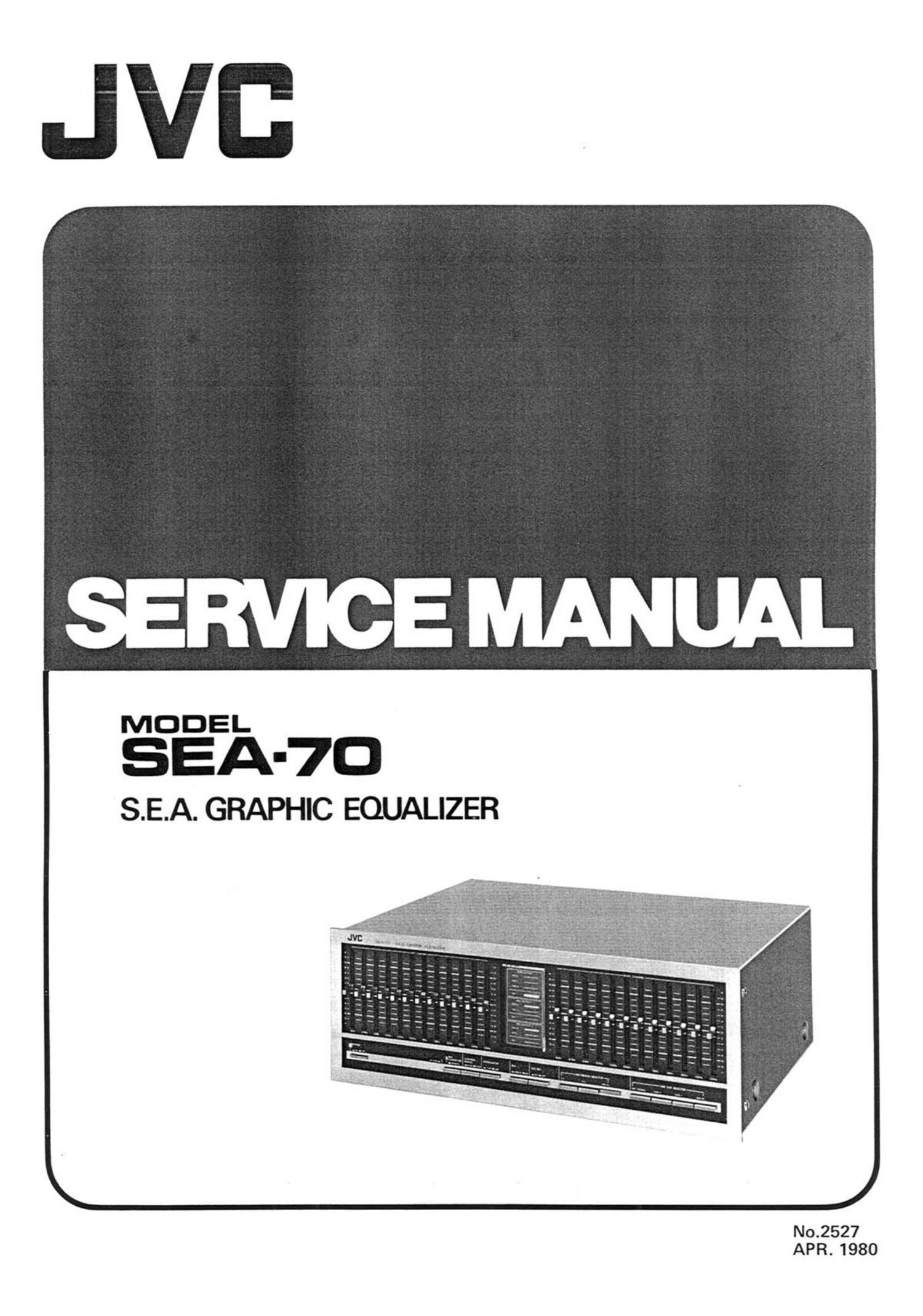
Jvc SEA 70 Service Manual

This is the 18 pages manual for Jvc SEA 70 Service Manual.
Read or download the pdf for free. If you want to contribute, please mail your pdfs to info@audioservicemanuals.com.

Page: 1 / 18
left right
Jvc SEA 70 Service Manual

Extracted text from Jvc SEA 70 Service Manual (Ocr-read)


Page 2

Contents

1. Specifications ........................
2. Removal Procedure of Top Cover ...........
3. Main Parts Location
3-(1) Top View .......................
3-(2) Front View ......................
3-(3I Rear View .......................
Exploded View .......................
Block Diagram ........................
Service Precaution .....................
Adjustment Procedures
7-H) Center Voltage Adjustment ...........
7-(2I Gain Adjustment ..................
8. Printed Circuit Board Assy and Parts List
8-(1I TXX-259 Functions Switch & Pin-jack
P.C. Board Ass'y ............
8-(2) TXX-260 S.E.A. Resonator P.C. Board
Ass'y ...................

$95?

1 . Specifications

Circuitry
Buffer amplifier

: FET-equipped, lCL-input, dou-

7

9

bIe differential, equiphase-feed-

back circuit.
: Double-differential input, DC
configuration circuit.
Semiconductor-L cuicuit : Transistor-Inductor cuircuit.

S.E.A. amplifier

8-(3I TXX-277 AC Socket & Fuse P.C. Board

Ass'y ................... 10
8-(4) TAO-515 Power Supply & S.E.A. Amp.

P.C. Board Ass'y ............ 11
9. Accessories List ....................... 13
10. Packing Materials ...................... 13

11. Parts List with Specified Numbers for Designated
Areas .............................. 13
12. SEA-70 Schematic Diagram ............... 14
13. Connection Diagram .................... 16

Warning:

When placing the parts marked with A , be sure to use
the designated parts to ensure safety.

Total harmonic distor-
tion

Intermodulation distor-
tion

Gain

S/N ratio

: 0.003 % (20 Hz - 20 kHz, rated

output)

: 0.003 % (with all S.E.A. controls

positioned at "0")

: 10 - 100,000 Hz (+0, -2 dB)
: 118 dB (at rated output, IHF A-

Input Section network short-circuited)
SEA INPUT : Input impednace 47 k-ohms 0001 section
TAPE MONI : Input impedance 47 k-ohms SEA center frequencies : 16 Hz, 31.5 Hz, 63 Hz, 125 Hz,
Output section 250 Hz, 500 Hz, 1 kHz, 2 kHz,
SEA OUTPUT : Output impedance 100-ohms 4 kHz, 8 kHz, 16 kHz, 32 kHz
TAPE REC : Output impedance 100-0th SEA control range 1 112 dB/i6 dB
(during SEA-recording) General
Rated output : 2 V RMS (with all S.E.A. con- Power source : See attached table
trols positoned at "0") Dimensions : 420(W) x 159(H) x 318(0) mm
Max. output : 8 v RMS (with all S.E.A. con- Weight : 6 kg
trols positioned at "0")
Power Specifications
EUROPE, U.K. & MILITARY MARKET &
CANADA 8 USA AUSTRALIA OTHER AREA
Power Supply AC 120 V», 50/60 Hz AC'110/120/220/240 V» AC 110/120/220/240 V'v
selectable, 50 Hz selectable, 50/60 Hz
Power Consumption 25 W 25 W 25 W
Power Outlet Fitted Not fitted Fitted
Fuse (PrimaryHF001) OMF61U1-R50 OMF51A2-R315L 0MF51A2-R315L
(0.5 A} (T315 mA) (T315 mA)

SEA-70
No. 2527