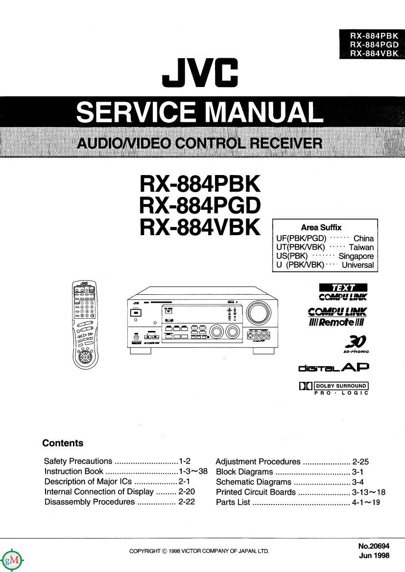
Jvc RX 884 PBK Service Manual

This is the 124 pages manual for Jvc RX 884 PBK Service Manual.
Read or download the pdf for free. If you want to contribute, please mail your pdfs to info@audioservicemanuals.com.

Page: 1 / 124
left right
Jvc RX 884 PBK Service Manual

Extracted text from Jvc RX 884 PBK Service Manual (Ocr-read)


Page 2

http : //getMANUAL . com

RX-884PBK/RX-884PGD/RX-884VBK l

-Safety Precautions

1.This design of this product contains special hardware and many circuits and components specially
for safety purposes. For continued protection. no changes should be made to the original design
unless authorized in writing by the manufacturer. Replacement parts must be identical to those
used in the original circuits. Services should be performed by qualified personnel only.

2. Alterations of the design or circuitry of the product should not be made. Any design alterations of
the product should not be made. Any design alterations or additions will void the manufacturers
warranty and will further relieve the manufacture of responsibility for personal injury or property
damage resulting therefrom.

3. Many electrical and mechanical parts in the products have special safety-related characteristics.
These characteristics are often not evident from visual inspection nor can the protection afforded
by them necessarily be obtained by using replacement components rated for higher voltage,
wattage, etc. Replacement parts which have these special safety characteristics are identified in
the Parts List of Service Manual. Electrical components having such features are identified by
shading on the schematics and by (its) on the Parts List in the Service Manual. The use of a
substitute replacement which does not have the same safety characteristics as the recommended
replacement parts shown in the Parts List of Service Manual may create shock, fire, or other
hazards.

4. The leads in the products are routed and dressed with ties, clamps, tubings, barriers and the
like to be separated from live parts, high temperature parts, moving parts and/or sharp edges
for the prevention of electric shock and fire hazard. When service is required, the original lead
routing and dress should be observed, and it should be confirmed that they have been returned
to normal, after re-assembling.

5. Leakage currnet check (Electrical shock hazard testing)

After re-assembling the product, always perform an isolation check on the exposed metal parts

of the product (antenna terminals, knobs, metal cabinet, screw heads, headphone jack, control

shafts, etc.) to be sure the product is safe to operate without danger of electrical shock.

Do not use a line isolation transformer during this check.

. Plug the AC line cord directly into the AC outlet. Using a "Leakage Current Tester", measure
the leakage current from each exposed metal parts of the cabinet , particularly any exposed
metal part having areturn path to the chassis, to a known good earth ground. Any leakage
current must not exceed 0.5mA AC (r.m.s.)

. Alternate check method
Plug the AC line cord directly into the AC outlet. Use an AC voltmeter having, 1,000 ohms
per volt or more sensitivity in the following 9

manneH Connect a 1,500 10W resistor paralleled ACVOLTMETER
by a 0.15 F AC-type capacitor between an exposed a (Having 1000
metal part and a known good earth ground. ohms/volts, _'
Measure the AC voltage across the resistor with the k 0" more sens'mm
AC voltmeter.
Move the resistor connection to eachexposed metal (3-15 F AC TYPE
part, particularly any exposed metal part having a -I-I- place this
return path to the chassis, and meausre the AC l , 'W\r _ probe on

' ' ' each ex sed
voltage across the reSIstor. Now, reverse the plug In 15009 10W metal pg).

the AC outlet and repeat each measurement. voltage

measured Any must not exceed 0.75 V AC (r.m.s.). Good earth ground

-- Warning

1.This equipment has been designed and manufactured to meet international safety standards.

2. It is the legal responsibility of the repairer to ensure that these safety standards are maintained.
3. Repairs must be made in accordance with the relevant safety standards.

4. It is essential that safety critical components are replaced by approved parts.

5. If mains voltage selector is provided, check setting for local voltage.

1-2

A CAUHON Burrs formed during molding may be left over on some parts of the chassis. Therefore,

pay attention to such burrs in the case of preforming repair of this system.

Page 19

RX-884P/RX-884V

usufiua

cm

.3...me 2.3...

.3 s... .afisfigfl 3.3 an.
|§6 3.9: Sfiiifi
3.52.50 $328... 3.8

.6 3.2.33: 2.. .35.? a
:38... 3.5.53 9.1. .38. $23. :2»... £2... .3. a 23.. a 85.3..
Ewe... -358. 52. a... u::c.._:m 533.. .. EB 4.2.. o... 9.52.. c.5956 Eon. 5...:
.33.. a. E. 6:. 5.... .a . ER... is 2.. $.53. .53.... 3.8 5.: 58:» D5...... 3 .§::::8
we»... 0...... 58. 3:3... .5. :. Eon. 2:3 23...... 22: : 855:... 2 .3... :.
259......m .33.; 30>»
.32. 3...... 2.3...
2 9.6.8.: biogacia 332%
2. :3 a»... a... 3.8 .5:
A ER. .3
.382 ME. .33. :41. 252.5 BBQ 5.; .o A E
m... .3 .35.... 9n m... 9...»: . WM 2.. 9.53. .335 3.8. a... 3:85
22.328 mm: 2.. 53:8 . 252.9. E .fifigs 2.. .25: s .3...
.2... :2 is... £8 £3. 3...... 2.. 3.2.
3% 2m 3 m S. o . ...
ES 3.. ... A. . II E: .53: 3...... .:.::..:m 3.2.
.22..
.03... 2.3:... 2..
S 3.2. as. 3.. =8 :9» .5...qu 2... 5.3
E E§.d g
..:..8. .22.. 9:2... .3.
,. .Vfiflmfiw .. .5» no...» .2: £5.53 .559... $2..
\. , 2:20 53 0.5... A .awugem Gown. 2.2.3.. o... .o Evin-o EESE. .8:-
\ x 2.. o.» 655. 3...... .5. 22:8 6......
. 1% 5......2..:.._.:...:.§:

\ 2.. .E :13... u... 2:... 52...... .25..
\ . 8...... u... .5 .no..ou=u. .5. 52...; 3.3....
5%.. 3.. 5:2 .25. .025 43......
.5... w :02... E: 338:2 2.... \
....:S 52.9.. E... 2...... 52... 3 3.2.8
3:.» 8 E... 52.8 a g. .25.. .252 2:.

Hum ESH 05 HQ

. /
WEEK-Uta. 3.3

23.5%
2.5.: a»: .1... 5...: v.52 3.5:...
a... 3:3,... 2 03...... .. 3...... u... E...

.25... mmn. m... .3 E... .838
3...... a... .5289 5......

FEED»... FE. .e u... a a: 9...... 328.3.

5:352 .53 :o :23... .o .2... a...

.2... m. .8... 27.2.73. 2: .223... .5... :.

Ea 2.. a 33... awn 2.. 3 3.5.5.... 32.. e... 225...... .0 was.

. a... 3:53 03.5.... s 8.: 2%.... m.
6...... .588 2:25 3.8 .5 i=2...
.3... 3 an... 3851mm 2... . 30:35». a .. 3 Sean 2:25 3.3..
.60.»... a 5:. :o. .9... QB... 0.20:...2 2:.
Ii 25:. UEQEEA-M.

m8... 9:. m... 8: .2. =8 :9 .
«8:5: .aneoE E

gaspinm. .8me mu: haw
um... 8:. 3.9... Em... 5.8. m3... SEEM. .E: $5... .8388... 2.3.8... 5%.... 5;. $2.. 220....
.Qm I 25:. «Summon... .mcfim .338 min m... .3 8.3 $5.. $3.35 hammock. 3.395% 5......5 2E

8.55. mmn 2.. :3. I

an

.25 3:... 35.2.5... 2.. 3%.... DOSE-m: $5 2... 32.23.... 32. a gram

3qu :3 a. on...

a. 0.... 8w

3.3

.3055... 5...... a... :e a... m. as. 32.2..
2...: :EE..:. 05 2...: was; 3.952.... 5... a.

$53.80..

.. «he: .35»... 3:: .2...- s n :5 . .8. 32.... .n

28 29.5.. as. u... 2 8......
3 :3 .6553... a... 2:»... E 2.:

.22 a... 33.8.. 3.3.8.2258 .. .55.... .
.26. .5 g5... 3.5.8.. .. 3.5.... .

3...... a... .5 as

u. an.» «:23... u... .: 538...... a... 2...: $5 .9552.
38.3 2.. .: .95. «.mm 2: was: s 00.. .59.). E; .u

9-5: 4:!»

Ea... o... :: Ex...» :5. :2. 3:: .e 5... $5....
as: .3252. 2... 5:: 2.5.8.... 53:4 gm 2»... ..

5...... w :2. a... 5.5.9.5.

<5 0... 3%.... 2 in»: 55¢. =5 causal... .50. £8. a. 2.; 5.. on .5» a

5:: .952. «:2. 2... .5

awn-02x3... Em. bin»... 2... .5533... <5 .55 :5.» BB. 2... 3.5.: :3 =o>

8.3.). $5 2.. mam:

1-19

usnfiua

Page 50

RX-884P/RX-884V

3. Functions

:1]: Symbol I/O Function no Symbol t/O Function
1 GNDA --- Ground 41 MOSI 1/0 SPIMaster-Out-Slave-In
2 m o MemoryChipSelect 42 E r SPISIaveSelect
a MOSS O No use 43 HRQE |/o HostRequest
4 MA14 0 Memory Address 44 GNDS ... Ground
5 MA13 O MemoryAddress 45 SD02 0 Serial DataOutput
6 VCCA --- Address Bus Power 46 SD01 0 Serial Data Output
7 MA12 0 MemoryAddress 47 5000 0 Serial DataOutput
a GNDA --- Ground 48 VCCS ... Srial Interface Power
9 VCCQ --- Quiet Power 49 SCKT I/O Serial C|ockTransmit
10 GNDO Ground 50 WST I/O Word SelectTransmit
11 MA11 0 Memory Address 51 SCKR IIO Receive Seriat Clock
12 MA10 0 MemoryAddress 52 GNDD ... Ground
13 MA9 0 Memory Address 53 VCCQ ... Quiet Power
14 MAS O MemoryAddress 54 GNDS --- Ground
15 GNDA Ground 55 WSR |/0 Word Select Receive
16 MA7 O MemoryAddress 56 SUN | Serial Datalnput
17 VCCA --- Address BusPower 57 SDIO | Serial Datalnput
18 MAG 0 MemoryAddress 58 D80 0 Nouse
19 MAS 0 Memory Address 59 DSI no No use
20 MA4 0 Memory Address 60 DSCK W No use
21 GNDA --- Ground 61 FR | Debug Request
22 MA3 0 Memory Address 62 MD7 I/o Data Bus
23 MA2 O MemoryAddress 63 MD6 I/O Data Bus
24 MA1 0 MemoryAddress 64 MD5 I/O Data Bus
25 MAD 0 Memory Address 65 M04 IIO Data BUS
26 SCK IIO SPI Serial Clock 66 GNDO ... Ground
27 EXTAL | ExternalClock/Crystal 67 MDB IIO DataBus
28 VCCQ Address Bus Power 68 M02 IIO Data Bus
29 GNDQ -- Ground 69 M01 |/0 Data Bus
30 PINIT l Ground/PLLInitialization 70 VCCD --- Data Bus Power
31 GNDP --- Ground 71 MDO I/O Data Bus
32 PCAP I PLL FilterCapacitor 72 GNDO ... Ground
33 VCCP PLL Power 73 GP|03 I/o No use
34 GNDS Ground 74 GPI02 1/0 No use
35 MISO I/O SPlMaster-ln-Slave-Out 75 GPIO1 1/0 No use
36 RESET I Reset 76 GPIOO l/O Control Signal with I0631
37 MODA I ModeSeIect 77 MFtD 0 Memory Read Strobe
38 MODB I Ground 78 MWR 0 MemoryWritestrobe
39 MODC I ModeSelect 79 M031 0 No use
40 VCCS -<- Seriatlnterface Power 80 M082 0 No use

2-12