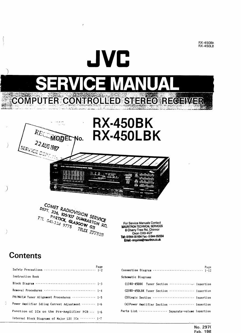
Jvc RX 450LBK Service Manual

This is the 69 pages manual for Jvc RX 450LBK Service Manual.
Read or download the pdf for free. If you want to contribute, please mail your pdfs to info@audioservicemanuals.com.

Page: 1 / 69
left right
Jvc RX 450LBK Service Manual

Extracted text from Jvc RX 450LBK Service Manual (Ocr-read)


Page 1

Fix-4508K
RX-450LB

77a: GUM
441"} 34 QAGO £42 TON For Service Manuals Contact
9775 W (5;; ml munrmon TECHNICAL sgnvwzs
Tag; 3 Cherry Tree Rd. Chmnor
; [75 0x00 OX9 40!
m Tet- 018444551 94 Fac- oywasasu
Wrerqurwmmfl
Page
Safety Precautions .............................. 1-2 Connection Diagram ........
Instruction Book Schelatic Diagrams
OCR may --------------------------------- 13 (URX'4SOBK Tuner Section ------------- av Insertion
Rennval Procedures ----------------------------- 1-4 (2)RX-450LBK Tuner Section --------------- Insertion
FM/HH/Lw Tuner AIignIent Procedures ----------- 15 (3)Logic Section ------------------------ Insertion
Pouer Alplifier IdIing Current Adjustment 1-6 (Power Alplifier Section --------------- Insertion
Function of ICs on the Pre~AmpliEier PCB 1-6 Parts List ---------------- Separate-value Insertion
Internal Block Diagrals of Major LSI [Cs --------- I~7
No. 297(

Feb 198

Page 2

Fix-4508K
RX -4 SOLBK

Safety Precautions

1. The design of this product contains special hardware and

many circuits and components specially for safety pur-
poses.
For continued protection, no changes should be made to
the original design unless authorized in writing by the
manufacturer. Replacement parts must be- identical to
those used in the original circuits. Service should be
performed by qualified personnel only.

2. Alterations of the design or circuitry of the product
should not be made. Any design alterations or additions
will void the manufacturers warranty and will further
relieve the manufacturer of responsibility for personal
injury or property damage res "

_ .g therefromu

3. Many electrical and mechanical parts in the product
have special safety-related characteristics. These charac-
teristics are often not evident from visual inspection nor
can the protection afforded by them necessarily be ob-
tained by using replacement components rated for higher
voltage, wattage, etc. Replacement parts which have
these special safety characteristics are identified in the
Parts List of the Service Manual. Electrical components
having such features are identified by shading on the
schematics and by l A l on the Parts List in the Service
Manual. The use of a substitute replacement which does
not have the same safety characteristics as the recom-
mended replacement part shown in the Parts List of
the,$ervice Manual may create shock, fire, or other

hazards.

4. The leads in the products are routed and dressed with
ties. clamps. tubings, barriers and the like to be sepa-
rated from live parts, high temperature parts, moving
pans and/or sharp edges for the prevention of electric
shock and fire hazard.

When service is required, the original lead routing and
dress should be observed. and it should be confirmed
the they have been returned to normal, after reassembl-

mg.

5. Leakage current check

(Electrical shock hazard testing)

After re-assembling the product. always perform an

isolation check on the exposed metal parts of the

product (antenna terminals, knobs, metal cabinet,

screw heads, headphone jack, control shafts, etc.) to be

sure the product is safe to operate without danger of

electrical shock.

Do not use a line isolation transformer during this check.

- Plug the AC line cord directly into the AC omlet.
Using a Leakage Current Tester", measure the
leakage current from each exposed metal part of the
cabinet, particularly any exposed metal pan having a
return path to the chassis, to a known good earth
ground. Any leakage current must not exceed 0.5 mA
AC (r.m.s.).

0 Alternate check method.
Plug the AC line cord directly into the AC outlet. Use
an AC voltmeter having 1,000 ohms per volt or more
sensitivity in the following manner. Connect a 1,500 9
10 W resistor paralleled by a 0.15 uF AC-type
capacitor between an exposed metal part and a known
good earth ground.
Measure the AC voltage across the resistor with the
AC voltmeter.
Move the resistor connection to each exposed metal
part, particularly any exposed metal pan having a
return path to the chassis, and measure the AC
voltage across the resistor. Now. reverse the plug in
the AC outlet and repeat each measurement. Any
voltage measured must not exceed 0.75 V AClr.m.s.).
This corresponds to 0.5 mA AClrms).

AC VOLTMETER
@ (Having 1000 ohms/volt.
or more sensitivrty.)
a c

0.15;} AC YVPE

Place this probe

r
l
l
l

I Before inserting the paper plug, please check that the voltage selector's setting corresponds with
Ithe line voltage in your area. If it. doesn't. be sure to reset. the voltage selector before operating

this equipment.

The voltage selector may be located on the rear or button of the unit. or underneath the platter.

:CAUTIUN : Before setting the voltage selector to the proper voltage. disconnect the power plug.

1J7 1M.» 7Q7fll

4% on each exposed
isoon row metal part.
Good earth ground
CHECK THE VOLTAGE SELECTOR'S SETTING - -

(Except for U.S.A., Canada. Australia. U.K. and Continental Europe)

-_-._-_____J

) .

Page 61

RX-4SOBK
RX-450LBK

Haw in insiaii tin batteries
Elnutzcn cu Batterter
Installation on piles
Integer! mi do battertlen
insiaiacton a. In pills

Hour In in. the prorirlded eonmciton bar
Verwendurig dev rliltgelleterlon lendnngs~
schlen.

Ullllsatlari a: la barre a. ldlmtnl tournle
Gebruilt an a: bilgeteve listultstut

Como umix-r la blrrrl a. conuwn oumlnlotrm

mi- onvni

For Service Manuals Contact
MAURITRON TECHNICN. SERVICES
8 Cherry Tree Rd, Chinnor
Oxori OX9 4QY
Tolt- 018444951694 Faxz- MW
Erot- Wmutitmmuk

6 Operation buttons for the tape deck/VCR]
DA |ape deck selected by me TAPE
CONTROL, VCR CONTROL or DA TAPE
CONTROL
E] (PAUSE/STILL): Press this button to
pause during playback or recording. To release
tnrs lunction, press the PLAY button
El (STOP): Press this button to stop
operation
E) (REC): While holding this button pressed.
press the PLAY (b ) button to record When this
button Is pressed with the PAUSE/STlLL ( || )
button. REC-PAUSE mode is activated.

IE : Press to last wind the tape from right to
lett.

E] (PLAY): Press this button to play a tape.
Et : Press to last thd the tape trorri left to
right.

Q MUTE
Press this button to instantly muste the sound.
To return the volume to its original level press
this button again, or press the BALANCE or
VOLUME button


0 VOLUME
Press the " " button to increase the volume
and the ' button to decrease rt

0 SEA LEVEL

When the SEA CONTROL button has been
pressed. these buttons can be used to atflust
the S EA levet ot the trequency band selected
by the SEA frequency band select buttons.

Battery
IHow to install the batteries (Fig. 16)
1. Slide the cover at the battery case in the
direction of the arrow to remove it
2. Install the provrded batteries (AA. SUM-3, R6.
1 5 V). with their polarities property placed.
3, Re-instatl the cover oi the battery use.
0 Battery me
The batteries can be used tor abom one year.
I Battery replacement time
When the distance at Whtch the remote control
unn tunctions begins to decrease, replace both
batteries.

Notes:

- When the remote control is operated too near
the receiver during AM reception. It my
nose lnterterence.

o The remote controt can be used up to about 5
III (25 ii) irorn the receiver.

0 How to use the provided connection bar (Fig.
17)
When usrng the RM-SFMSO with a compatibty-
designed remote control unit at a TV or other
component. connect the two units with the
connection bar.

Notes:

- For sarety. remove the bar when the units are
separated.

- To protect yoursell lrom the connection bars
exposed edges. remove the bar trorn the unit
atter draping it with a cloth.

0 Bedienlaslen hir Kassettendeck/DAT~
KassettendeckNideorekorder, gewihlt mit
Taste TAPE CONTROL, VCR CONTROL
oder DA TAPE CONTROL
E3 (PAUSE/STILL): Fur Pause wahrena
Wiedergabe oder Autnahme diese Taste
drucken Zum Freigeben oer Pause die PLAV-
Taste drunken
El (STOP): Diese Taste zum Stoppen des
Bandlauts orueken
[El (REC): Zum Autnahmestart diese Taste
gedruckt halten und die PLAY lb) Taste
betéitigeri Wenn diese Taste zusarhmen mit oer
PAUSE/STlLL-Taste ( I I) gedrUckt wirdv wird
aut Aulnahmepause geschattet.

El : Zum schnetlen Spulen dos Banoes Von
rechts nach links drese Taste dri'rcken

E] (PLAY): Fur Wieoergabe diese Taste
dnJcken.

E} : Zum schnellen Spulen des Bandeslrnks
nach rechts diese Taste chicken.

0 Mmpiungs-Tasie (MUTE)

Dutch Dru'cken dieser Taste wird die
Lautstarke augenblicklich gedamptt und dutch
erneutes Drficken dieser Taste oder der
BALANCE-Oder IOLUMEJaste die verige
Lautstarke wieder hergestetlt.

0 LautstHrKe-Tnste (VOLUME)

Zum Emijhen oer Lautstarke die Seite "+" und
zum Verminttern der Lautstarke die Seile "-
drucken

0 SEA-Pegel (SEA LEVEL)

Nach Betattgen dei SEA CONTROL-Taste
kann mit diesen Tasten das fiber are SEA-
Frequenzband-Wahltzsten bestimmte Band
eingesteltt werden

Bdttuie

I Elnsetzen oer Batterten (Abb. 16)

1. Ben Batterielachdeckel in Pteilrichturig

abschieben.

2. Die mrtgelieterten Batterieri (AA, SUM-3. R6: t.5

V) unter Beachtung der Polaritat einsetZen.

3. Den Batterielachdeckel wieder anoringen,

- Lebenadauer der BatterIen
Die Lebensdauei dei Batterien betragt etwa ein
John

0 Zettpunkt zum Auswechsetn our Batterien
Wenn ore Entternung, in der die Fern-
bedienungseinheit arbeitet. abnirnmt, mussen
oeide Batterien ausgewechsett weroen

Hinweiu:

OWenn die Ferribedlenungselnheit bet MW-
Emptang zu none am Ernpranger Verwendel
wird, kann sic lriterterenastfirungen bewtrken.

cote Fembedtenung kann bis In other
Entternung von etwa 8 hi voni Emptinger
vemendet warden

OVerwendung der mitgefleterten Verbindungy
schierie (Abh. 17)
Bei Gebrauch der RM-SHASO zusammen mit
einer andeien Fernbedienung mit kompatiblem
Design (TV-Gerat etc.) are beioen Einheiten mit
Hitte der Verbindungsschiene verbiriden.

Hlnweise'

eAus Sicherheitsgrijnden die Verbtndimga-
schlene bei Nlohtgehrauch abriehmen.

0 Zum Sdiutz vor Verletzungen dle
Verbindungsschiene vor Ahnatirne mit etnem
Tuch etc Ibdedten.