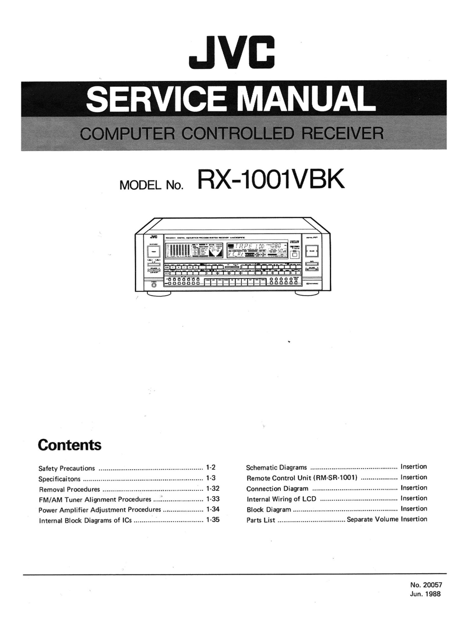
Jvc RX 1001 VBK Service Manual

This is the 58 pages manual for Jvc RX 1001 VBK Service Manual.
Read or download the pdf for free. If you want to contribute, please mail your pdfs to info@audioservicemanuals.com.

Page: 1 / 58
left right
Jvc RX 1001 VBK Service Manual

Extracted text from Jvc RX 1001 VBK Service Manual (Ocr-read)


Page 1

JVB

SERVICE MANUAL

MODEL No. RX-1 OOlVBK

Contents

Safety Precautions ...................................................... 1-2
Specificaitons .............................................................. 1-3
Removal Procedures .................................................... 1-32
FM/AM Tuner Alignment Procedures ..................... 1-33
Power Amplifier Adjustment Procedures .................. 1-34
Internal Block Diagrams of le .................................... 1-35

Schematic Diagrams ............................................. Insertion
Remote Control Unit (RM-SR-1001) ................... Insertion
Connection Diagram ............................................ Insertion
Internal Wiring of LCD ........................................ Insertion
Block Diagram ...................................................... Insertion
Parts List ................................... Separate Volume Insertion

No.20057
Jun.1988

Page 2

rSafety Precautions

1. The design of this product contains special hardware and many circuits and components specially for safety purposes.
For continued protection, no changes should be made to the original design unless authorized in writing by the
manufacturer. Replacement parts must be identical to those used in the original circuits. Service should be per-
formed by qualified personnel only.

2. Alterations of the design or Circuitry of the product should not be made. Any design alterations of the product
should not be made. Any design alterations or additions will void the manufacturer's warranty and will further
relieve the manufacturer of responsibility for personal iniury or property damage resulting therefrom.

3. Many electrical and mechanical parts in the product have special safety-related characteristics. These characteristics
are often not evident from visual inspection nor can the protection afforded by them necessarily be obtained by
using replacement components rated for higher voltage, wattage, etc. Replacement parts which have these special
safety characteristics are identified in the Parts List of Service Manual. Electrical components having such features
are identified by shading on the schematics and by l A ) on the Parts List in the Service Manual. The use of a sub-
stitute replacement which does not have the same safety characteristics as the recommended replacement part shown
in the Parts List of Service Manual may create shock, fire, or other hazards.

4. The leads in the products are routed and dressed with ties, clamps, tubings, barriers and the like to be separated from
live parts, high temperature parts, moving parts and/or sharp edges for the prevention of electric shock and fire hazard.
When service is required, the original lead routing and dress should be observed, and it should be confirmed that they
have been returned to normal, after re-assembling. 7 1

5. Leakage current check (Electrical shock hazard testing)

After re-assembling the product, always perform an isolation check on the exposed metal parts of the product

(antenna terminals, knobs, metal cabinet, screw heads, headphone iack, control shafts, etc.) to be sure the product

is safe to operate without danger of electrical shock. I

Do not use a line isolation transformer during this check.

0 Plug the AC line cord directly into the AC outlet. Using a "Leakage Current Tester", measure the leakage current
from each exposed metal part of the cabinet, particularly any exposed metal part having a return path to the
chassis, to a known good earth ground. Any leakage current must not exceed 0.5 mA AC (r.m.s.).

0 Alternate check method
Plug the AC line cord directly into the AC outlet. Use an AC voltmeter having 1,000 ohms per volt or more sensi-
tivity in the following manner. Connect a 1,500 $2 10 W resistor paralleled by a 0.15 pF AC~type capacitor be-
tween an exposed metal part and a known good earth ground.

Measure the AC voltage across the resistor with the AC VOLTMETER
AC vonmeter. T (Having 1000 ohms/volt,

. _ or more sensitivity.l
Move the resistor connection to each exposed metal
part, particularly any exposed metal part having a
return path to the chassis, and measure the AC volt-
age across the resnstor. Now, reverse the plug in the Place W9 Kobe
AC outlet and repeat each measurement. Any voltage _ on each was,
measured must not exceed 0.75 VAC (r.m.s.l. This 15000 10w metal part.
corresponds to 0.5 mA AC (r.m.s.).

Good earth ground

Warning

This equipment has been designed and manufactured to meet international safety standards.

It is the legal responsibility of the repairer to ensure that these safety standards are maintained.
Repairs must be made in accordance with the relevant safety standards.

It is essential that safety critical components are replaced by approved parts.

If mains voltage selector is provided, Check setting for local voltage.

PPPN.

1-2 (No. 20057)

Page 14

DOWN (< )IUP l> ): Select the required character,
number or symbol to be input by pressing DOWN or UP
button. After the required alphanumeric character is
displayed, press the CHARACTER button again to move to
the next character. By repeating this procedure, input the
station name or title as required. Titles can be up to five
alphanumeric characters long.

ENTER: After completing the title, press this button to
store it in memory.

0 AUTO MEMORY

After setting the stop level using the STOP LEVEL button,
press this button and then any of the TUNER 10-KEY
buttons to scan and preset broadcasts automatically. Start-
ing from the frequency being displayed the tuner tunes to
increasingly higher frequencies, until a broadcasts is tuned
in. Its signal strength is then shown in dB for one second
and the channel number you have pressed earlier flickers
for three seconds. If you dont wish to store this station in
memory, press this button within 4 seconds; the dB indica-
tion is shown and the scan function starts again. Otherwise,
the MEMORY indicator and channel number light. together
and the frequency is stored in that channel. Then the next
channel number is shown and upscanning restarts, as the
tuner automatically searches for a frequency to store in the
next channel. This process continues until the highest
numbered channel preset stations has a frequency stored in
its memory.

If the upper limit of the frequency band is reached before
this happens, the upper limit of the frequency is shown
with dB displayed instead of the channel number.
Otherwise, when this process ends, the last frequency tuned
to and its corresponding channel number are displayed. If,
while this operation is taking place within a partiCUlar
broadcast band, that same broadcast band button is press-
ed, the operation stops and the broadcast currently being
tuned to is heard. If a different broadcast band button is
pressed, the operation stops and the broadcast last tuned to
when that band was listened to is heard.

Note:

0 To cancel the auto memory function, press any of the
buttons in the tuner section other than the AUTO
MEMORY button.

® MEMORY

Press this button, and the MEMORY indicator will light
to show that it is ready to receive a memory setting. Press-
ing the station select button while the MEMORY indicator
is lit (for about 5-secondsl stores the station in the specified
memory. At this time. the channel number is shown in the
display.

a TUNING DOWN/UP

DOWN ( quency.

UP (>): Press this button to tune to a higher frequency.
Holding either button pressed for more than 1 second and
then releasing it starts auto tuning. When a broadcast is
received, tuning will stop. If either button is held down,
scanning continued even when a broadcast is received. In
auto tuning, pressing either button stops scanning. When
tuning toward higher frequencies, if the upper limit fre-
quency is reached, the frequency will change to the lower
limit and then auto tuning restarts in the direction of

1-14 (No. 20057)

increasing frequency. When tuning toward lower frequen-
cies, if the lower limit is reached, the frequency will change
to the upper limit and auto tuning restarts in the direction
of lower frequencies. The same operation is also performed
in AM tuning.

Each time these buttons are tapped, the FM frequency will
change in 100 kHz steps. and the AM frequency in 10 kHz
steps.

Q BALANCE (L/R)

This control is used to adjust the balance between the left
and right speakers. Tap the L side to shift the balance to
the left by one step and the R side to shift to the right.
Holding the button pressed changes the balance continu-
ously. The BALANCE indicator in the display shows the
current balance setting.

0 MUTE

When this button is pressed, the G COMPU LINK COM-
MUNlCATION SYSTEM indicator displays "MUTE",
and the sound will be muted instantaneously. To return
the volume to its original level, press this button again, or
press the BA LANCE or VOLUME button.

0 VOLUME (UP/DOWN)

Adjust the volume of speakers or headphones with this
button, Press the > (up) side once to increase the volume
by one step, and the < (down) side once to decrease it
by one step; this level is shown by the VOLUME indicator.
Holding down either side of this button will cause the
volume to rise or fall continuously.

Page 34

Power Amplifier Adjustment Procedures

I ldling Currenterdjustment
1.

2.

. Set the volume control to minimum

Trun VR701 and VR702 fully counter-
lockwise before the power switch on.
Warm up at least 5 minutes before
adjustment.

Must keep the heatsink to prevent over-
heating before adjustment.

during this adjustment.

Connect a DC voltmenter to R773
resistors leads for left channel, or
to R774 for right channel.

Adjust VR701 for left channel, or VR 702 for right
channel, so that the DC voltmeter becomes SmV
t3mV.

I Power Supply switching circuit Adjustment
(Except of the USA. and Canada.)

1.

2.

3.

Connectan an AC voltmeter and an oscilloscope to the
speaker terminal.

Before turning the power ON, turn the semi-fixed re-
sistors (VR055 for the left channel and VR056 for
the right) on the power amplifier PC Board fully
countercloskwise.

Turn the power ON and provide a 100 Hz sine wave

l Confirm the waveforms for surround effects

Dolby Surround

@PPN.

Dolby surround

1.
2.

1-34 (No.

Set the D.A.P switch to "ON".

Set the 4CH indicator to "ON".

Set the SEA switch to OFF".

Set the Dolby surround to "ON".
Provide a sine wave signal 100Hz, 200mV
p~p to the right channel of CD input
terminals.

Connect the X-axis of oscilloscope to the
input signal and the Y-axis to the right
channel of speaker terminals.

Adjust the volume control to 200mV
p-p at the right channel of speaker
terminals.

Set the oscilloscope to X-Y axis.
Confirm the waveform. (Fig-1)

Fig.4

Set the "Delay Time" to 2, 3 and 4.
Provide a sine wave signal 100 Hz,
200 mVp-p to the left channel of CD
input terminals.

Connect the X-axis of oscilloscope to the
input signal and the Y-axis to the left
channel of "REAR PR E. OUT".

Set the "SURROUND BALANCE" on 1.
the rear panel to center position.

Adjust the "REAR LEVEL volume"

@VR701

.l-Q) . Power Amp PC Board
RX- 100W / '

Dolby Surround

Set the "Deley Time" to 3.

2. Provide a sine wave signal
200 mV p-p to the right channel of CD

L-ch

Fig.-4

l' R773 l

R771. '

R-ch

VROSS VROSG

@VR702

to the left (or right) channel of the CD input termi-
nals.

4. Connect a 752 dummy load to the speaker terminal

and adjust the volume control so that 29V is output.
At this time, minimize the output level of the other
channel with the BALANCE control.

5. Turn the semi-fixed resistor lVR055 for the left

channel or VR056 for the right) slowly clockwise,
and stop when the output waveform begins clipping
on the oscilloscope.

6. Replace the 752 dummy load with an 89 one, and

Note:

confirm that the output waveform does not clip.

This adjustment should be performed for the channels
one at a time.

4. Adjust the "REAR LEVEL volume" and
"Volume control" to 200 mV p-p at the
right channel of "REAR PRE. OUT".

5. Set the oscilloscope to X-Y axis.

6. Confirm the waveform. (Fig-5)
Fig.5

LIVE CLUB

1. Set the Live Club to ON.

2. Provide a sine wave signal 100 Hz,
200mVp-p to the left channel of CD
input terminals.

3. Connect the X-axis of oscilloscope to the
input signal and the Y~axis to the left
channel of "R EAR PRE. OUT.

4. Set the "Room size to 3, Liveness to
3 and "Wall type to 2.

5. Adjust the "REAR LEVEL volume and
"Volume control" to 200 mV at the left
connel of "REAR PRE. OUT".

6. Confirm the waveform. (Fig-6)

100 Hz,

and Volume control to 200mV at the
left channel of "REAR PRE. OUT"

Set the oscilloscope to X-Y axis.
Confirm the waveforms. (Fig-2.3.4)

20057)

input terminals.

. Connect the X-axis of oscilloscope to

the input signal and the Y-axis to the
right channel of speaker terminals.

Fig.5