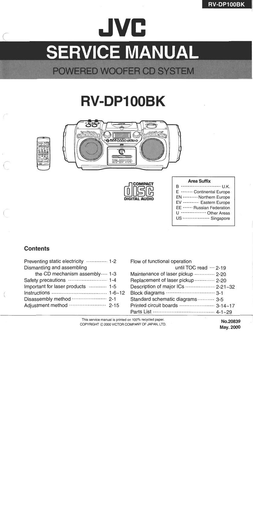
Jvc RVDP 100 BK Service Manual

This is the 90 pages manual for Jvc RVDP 100 BK Service Manual.
Read or download the pdf for free. If you want to contribute, please mail your pdfs to info@audioservicemanuals.com.

Page: 1 / 90
left right
Jvc RVDP 100 BK Service Manual

Extracted text from Jvc RVDP 100 BK Service Manual (Ocr-read)


Page 1

RV-DP100BK

JVB
SERVICE MANUAL

RV-DP1OOBK

007m
Area Suffix
COMPACT B ________________________ U-K.
E ------- Continental Europe
DIGITAL AUDIO EN --------- Northern Europe
EV ---------- Eastern Europe
EE ------ Russian Federation
U """"""""" Other Areas
US ---------------- Singapore
Contents
Preventing static electricity ------------- 1-2 Flow of functional operation
Dismantling and assembling until TOC read 2-19
the CD mechanism assembly---- 1-3 Maintenance of laser pickup ------------ 2-20
Safety precautions ------------------------ 1-4 Replacement of laser pickup--- 2-20
Important for laser products ----------- 1-5 Description of major le ------------------ 2-21~32
Instructions --------------------------------- 1-6~12 Block diagrams ----------------------------- 3-1
Disassembly method ----- 2-1 Standard schematic diagrams ---------- 3-5
Adjustment method ---------------------- 2-15 Printed circuit boards --------------------- 3-14~17
Parts List ------------------------------------- 4-1~29
This service manual is printed on 100% recycled paper. ' No.20839

COPYRIGHT © 2000 VICTOR COMPANY OF JAPAN, LTD.
May. 2000

Page 2

. RV-DP1OOBK

Preventing static electricity

Electrostatic discharge (ESD), which occurs when static electricity stored in the body, fabric, etc. is discharged,
can destroy the laser diode in the traverse unit (optical pickup). Take care to prevent this when performing repairs.

1.1. Grounding to prevent damage by static electricity
Static electricity in the work area can destroy the optical pickup (laser diode) in devices such as CD players.
Be careful to use proper grounding in the area where repairs are being performed.

1.1.1. Ground the workbench
1. Ground the workbench by laying conductive material (such as a conductive sheet) or an iron plate over
it before placing the traverse unit (optical pickup) on it.

1.1.2. Ground yourself
1. Use an anti-static wrist strap to release any static electricity built up in your body.

(caption)
Anti-static wrist strap

1M0

' Conductive material
(conductive sheet) or iron plate

1.1.3. Handling the optical pickup

1. In order to maintain quality during transport and before installation, both sides of the laser diode on the
replacement optical pickup are shorted. After replacement, return the shorted parts to their original condition.
(Refer to the text.)

2. Do not use a tester to check the condition of the laser diode in the optical pickup. The tester's internal power
source can easily destroy the laser diode.

1.2. Handling the traverse unit (optical pickup)

1. Do not subject the traverse unit (optical pickup) to strong shocks, as it is a sensitive, complex unit.

2. Cut off the shorted part of the flexible cable using nippers, etc. after replacing the optical pickup. For specific
details, refer to the replacement procedure in the text. Remove the anti-static pin when replacing the traverse
unit. Be careful not to take too long a time when attaching it to the connector.

3. Handle the flexible cable carefully as it may break when subjected to strong force.

4. It is not possible to adjust the semi-fixed resistor that adjusts the laser power. Do not turn it

Page 21

RV-DP10OBK

Location of parts to be adjusted

lCassette handling mechanism lCassette handling mechanism (reverse side)

Head for recording, playing
and erasing the tape

Head azimuth adjusting a . .
screw (fast-forward) 83;ng flgfifififtm


-->

; CN31

Head for recording,

Head azimuth adjusting playing and erasing the tape
Head azimuth screw (rewind)

adjusting screw (fast-forward)

I Location of parts to be adjusted

VR37
Motor speed

TP
Bias oscillation frequency (wide pattern)

L301
Bias oscillation frequency

VFl31
Lch recording frequency (bias adjustment)

VR32
Rch recording frequency (bias adjustment)

2-16

Page 66

RV-DP1OOBK

Block No. E E E

Exploded view of general assembly and parts list

Front cabinet

4»2