Jvc RK 11 Service Manual 2

This is the 4 pages manual for Jvc RK 11 Service Manual 2.
Read or download the pdf for free. If you want to contribute, please mail your pdfs to info@audioservicemanuals.com.

Page: 1 / 4
left right
Jvc RK 11 Service Manual 2

Extracted text from Jvc RK 11 Service Manual 2 (Ocr-read)


Page 1

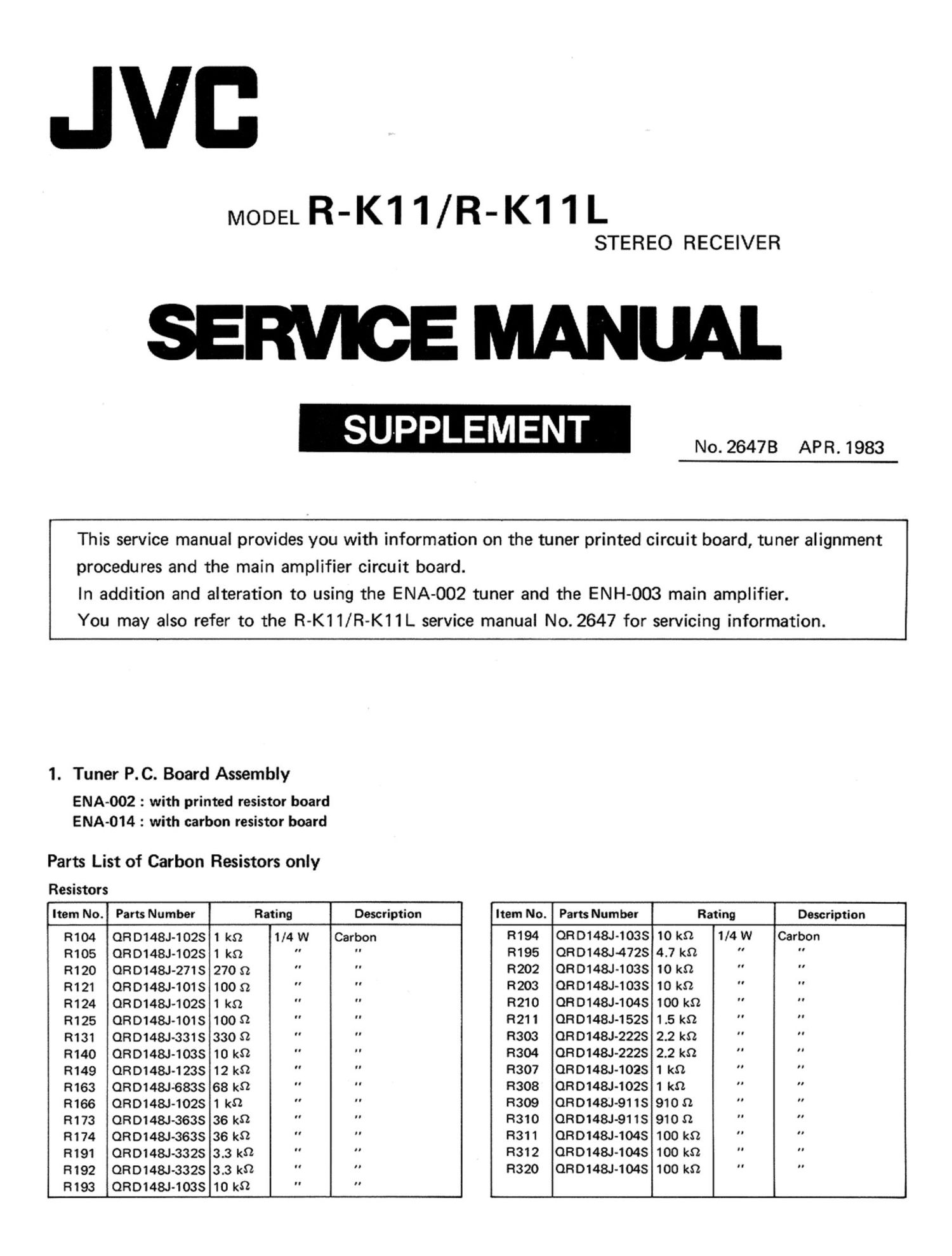
JVB

MODEL R-K11/R-K11L

STEREO RECEIVER

SERVICE MANUAL

SUPPLEMENT

No. 26478 APR. 1983

This service manual provides you with information on the tuner printed circuit board, tuner alignment
procedures and the main amplifier circuit board.

In addition and alteration to using the ENA-002 tuner and the ENH-003 main amplifier.

You may also refer to the R-K11/R-K11L service manual No. 2647 for servicing information.

1. Tuner P. C. Board Assembly

EMA-002 : with printed resistor board
EMA-014 : with carbon resistor board

Parts List of Carbon Resistors only

Resistors

Item No. Parts Number Rating Description Item No. Parts Number Rating Description
R104 QRD148J-102S 1 kn 1/4 W Carbon R194 QRD148J-103S 10 kn 1/4 W Carbon
R105 ORD148J-102S 1 kn " " R195 QRD148J-472S 4.7 kn " "
R120 ORD148J-271S 270 n " " R202 ORD148J-103S 10 kn " "
R121 ORD148J-101S 100 n " " R203 QRD148J-103S 10 kn " "
R124 ORD148J-102S 1 kn " " R210 ORD148J-1045 100 kn " "
R125 QRD148J-101S 1009 " " R211 ORD148J-152S 1.5 kn " "
R131 ORD148J-331S 330 $2 " " R303 QRD148J-222S 2.2 kn " "
R140 QRD148J-1038 10 kn " " R304 QRD148J-2228 2.2 kn " "
R149 ORD148J-1238 12 kn " " R307 ORD148J-1028 1 kn " "
R163 ORD148J-6838 68 k9 " R308 0RD148J-102S 1 kn " "
R166 QRD148J-102S 1 k9 " R309 ORD148J-911S 910:2 "
R173 ORD148J-363S 36 k9 " " R310 ORD148J-911S 910 n " "
R174 ORD148J-363S 36 k0 " " R311 QRD148J-1048 100 kn " "
R191 QRD148J-3328 3.3 k9 " " R312 ORD148J-1048 100 kn " "
R192 ORD148J-332S 3.3 kg " R320 QRD148J-1048 100 kn "
R193 ORD148J-1038 10 kn " "

Page 2

2. Specified Numbers in ENA-002/ENA-014 for Designated Areas

U.S.A. & Australia 8! U.K. 8: Republic of US. Military
Item No. Description Canada Europe West Germany Europe South Africa Market & Other
[31 El [with LW) [a OWN: [A]
L101 RF Coil EQR2306013 EQR2306-013 EOR2306-017 EOR2306-013 EOR2306-013 EQR2306-013
L103 RF Coil EOR2406-001 EQR2406-001 EOR 2406-001 EQR 2406-001 EOR 2406-005 EQR2406-001
R 168 Resistor QRD148J-3648 EVP314-7-B55 EVP314-7-855 EVP314-7-855 ORD148J-364S ORD148J-364S
R234 Resistor ORD149J-101S ORZOO52-680 0R20052-680 0R20052-680 QRD149J-101 S QRDl41J-101S

Note: ORD148J-3648 Carbon Resistor 360 m 1/4 W
EVP314-7-855 Semi-Fixed Resistor 500 kn

3. FM/MW (LW) Tuner Alignment Procedures

3-(1) PM Section
Alignment Location on ENA-OOZ/ENA-014 Tuner P.C. Board

Assembly 3
f 4
L 5.
6.
7
L101 201 8
© [32% .
L103 C. L102 215
© 6 ©
,3. :5)
S 1131 '1:
e T132 Tcz. TC3 TCZ TCl -*
133
915563 32
-C269 L252 L251
L G §
254
1.
mes lag; E:
213 2
R391 EE-l 1201 '
E 9
C282 3
t For Australia,Europc.W¢st Germany and U.K. only.)
4
5

E

Discriminator, Center Meter, Distortion and Signal Gain
1.
2.

Set to FM.

Connect an RF generator, 1 kHz modulation and 75 kHz
deviation, to the antenna terminals on the rear panel
through a dummy antenna.

. Connect an Oscilloscope, Distortion Meter and VTVM to

the Rec. Out jacks on the rear panel.

. Tune to a frequency where there is no broadcasting.

Connect a DC VTVM between TP130 and 131 .
Adjust the core of T131 for DC VTVM reading of 0
(zero) mV.

. Set the RF generator to 98 MHz.
. Set the dial pointer to 98 MHz.
. Adjust the core of T132 so that the distortion is mini-

mized at a value less than 0.4%.

Tracking and Sensitivity
Precaution: No adjustment is necessary. The tracking and

sensitivity have been adjusted properly and
completely at the factory. If any special reason
occasioned, take the following procedures care-
fully.

Low Frequency

Connect an RF generator to the antenna terminals on
the rear panel through a dummy antenna.

Set the RF generator to 88 MHz, a modulation of 1 kHz
and a deviation of 75 kHz to provide an input of 2 1.1V.

. Connect a VTVM and an Oscilloscope to the Rec. Out

jacks on the rear panel.

. Set the dial pointer to 88 MHz.
. Adjust the three coils L103, L102 and L101 in the

tuning gang to maximize the output.

High Frequency

6.

R-K11/L
No. 26478

7.
8.

9.

Set the RF generator to 108 MHz, a modulation ofl kHz
and a deviation of 75 kHz, to provide an input of 2 1.1V.
Set the dial pointer to 108 MHz.

Adjust the FM trimmers C114, TCI and T03 in the
tuning gang to maximize the output.

Repeat these high and low frequency adjustments alter-
nately until maximum sensitivity is obtained.

Note: After adjustment, confirm that the band cover is as

follows: [for West Germany only)
FM: Lower 87.5 MHz -300 kHz, Higher 108.0 MHz
+500 kHz