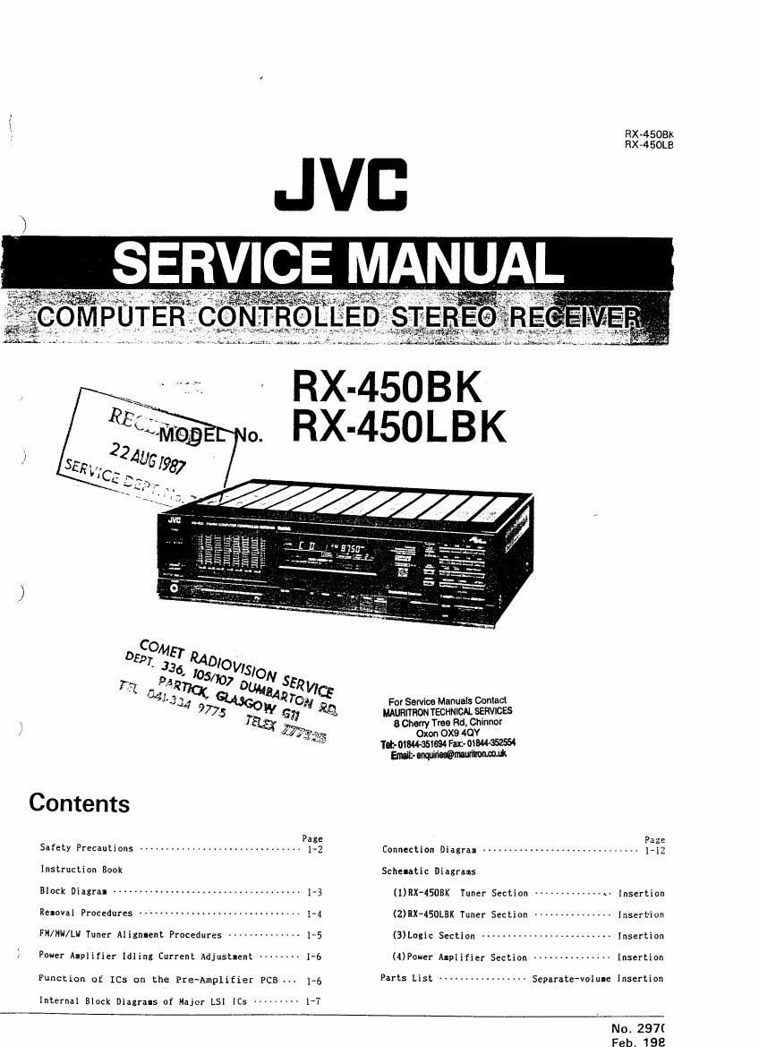
Jvc RC 450 BK Service Manual

This is the 70 pages manual for Jvc RC 450 BK Service Manual.
Read or download the pdf for free. If you want to contribute, please mail your pdfs to info@audioservicemanuals.com.

Page: 1 / 70
left right
Jvc RC 450 BK Service Manual

Extracted text from Jvc RC 450 BK Service Manual (Ocr-read)


Page 1

Fix-4508K
RX-450LB

77a: GUM
441"} 34 QAGO £42 TON For Service Manuals Contact
9775 W (5;; ml munrmon TECHNICAL sgnvwzs
Tag; 3 Cherry Tree Rd. Chmnor
; [75 0x00 OX9 40!
m Tet- 018444551 94 Fac- oywasasu
Wrerqurwmmfl
Page
Safety Precautions .............................. 1-2 Connection Diagram ........
Instruction Book Schelatic Diagrams
OCR may --------------------------------- 13 (URX'4SOBK Tuner Section ------------- av Insertion
Rennval Procedures ----------------------------- 1-4 (2)RX-450LBK Tuner Section --------------- Insertion
FM/HH/Lw Tuner AIignIent Procedures ----------- 15 (3)Logic Section ------------------------ Insertion
Pouer Alplifier IdIing Current Adjustment 1-6 (Power Alplifier Section --------------- Insertion
Function of ICs on the Pre~AmpliEier PCB 1-6 Parts List ---------------- Separate-value Insertion
Internal Block Diagrals of Major LSI [Cs --------- I~7
No. 297(

Feb 198

Page 2

Fix-4508K
RX -4 SOLBK

Safety Precautions

1. The design of this product contains special hardware and

many circuits and components specially for safety pur-
poses.
For continued protection, no changes should be made to
the original design unless authorized in writing by the
manufacturer. Replacement parts must be- identical to
those used in the original circuits. Service should be
performed by qualified personnel only.

2. Alterations of the design or circuitry of the product
should not be made. Any design alterations or additions
will void the manufacturers warranty and will further
relieve the manufacturer of responsibility for personal
injury or property damage res "

_ .g therefromu

3. Many electrical and mechanical parts in the product
have special safety-related characteristics. These charac-
teristics are often not evident from visual inspection nor
can the protection afforded by them necessarily be ob-
tained by using replacement components rated for higher
voltage, wattage, etc. Replacement parts which have
these special safety characteristics are identified in the
Parts List of the Service Manual. Electrical components
having such features are identified by shading on the
schematics and by l A l on the Parts List in the Service
Manual. The use of a substitute replacement which does
not have the same safety characteristics as the recom-
mended replacement part shown in the Parts List of
the,$ervice Manual may create shock, fire, or other

hazards.

4. The leads in the products are routed and dressed with
ties. clamps. tubings, barriers and the like to be sepa-
rated from live parts, high temperature parts, moving
pans and/or sharp edges for the prevention of electric
shock and fire hazard.

When service is required, the original lead routing and
dress should be observed. and it should be confirmed
the they have been returned to normal, after reassembl-

mg.

5. Leakage current check

(Electrical shock hazard testing)

After re-assembling the product. always perform an

isolation check on the exposed metal parts of the

product (antenna terminals, knobs, metal cabinet,

screw heads, headphone jack, control shafts, etc.) to be

sure the product is safe to operate without danger of

electrical shock.

Do not use a line isolation transformer during this check.

- Plug the AC line cord directly into the AC omlet.
Using a Leakage Current Tester", measure the
leakage current from each exposed metal part of the
cabinet, particularly any exposed metal pan having a
return path to the chassis, to a known good earth
ground. Any leakage current must not exceed 0.5 mA
AC (r.m.s.).

0 Alternate check method.
Plug the AC line cord directly into the AC outlet. Use
an AC voltmeter having 1,000 ohms per volt or more
sensitivity in the following manner. Connect a 1,500 9
10 W resistor paralleled by a 0.15 uF AC-type
capacitor between an exposed metal part and a known
good earth ground.
Measure the AC voltage across the resistor with the
AC voltmeter.
Move the resistor connection to each exposed metal
part, particularly any exposed metal pan having a
return path to the chassis, and measure the AC
voltage across the resistor. Now. reverse the plug in
the AC outlet and repeat each measurement. Any
voltage measured must not exceed 0.75 V AClr.m.s.).
This corresponds to 0.5 mA AClrms).

AC VOLTMETER
@ (Having 1000 ohms/volt.
or more sensitivrty.)
a c

0.15;} AC YVPE

Place this probe

r
l
l
l

I Before inserting the paper plug, please check that the voltage selector's setting corresponds with
Ithe line voltage in your area. If it. doesn't. be sure to reset. the voltage selector before operating

this equipment.

The voltage selector may be located on the rear or button of the unit. or underneath the platter.

:CAUTIUN : Before setting the voltage selector to the proper voltage. disconnect the power plug.

1J7 1M.» 7Q7fll

4% on each exposed
isoon row metal part.
Good earth ground
CHECK THE VOLTAGE SELECTOR'S SETTING - -

(Except for U.S.A., Canada. Australia. U.K. and Continental Europe)

-_-._-_____J

) .

Page 4

Service Manuals Contact
MAUHFM lTRON TECHNlCAL SERVICES
8 Cherry Tree Rd, Chllanl'
RXA4508K Oxon OX9 4QY
RX ASCLBK Tel:- 01844-351894 Fax: him-352554
Emailz- enqniriestaumunmuk

2. Removal Procedures

Power Amplifier PCB

,5
a
r:

e: n pinn- m

Tuner
PCB

-LCD
PCB

2-(3) Removal of Turier PCB

LReloVe two screws securing the antenna terlinai on
From switch the rear panel.

PC Board
Z.Loosen the screws securing the rear panel.

3.?uli out a plastic rivet ® securinx the tuner PCB.

LPull up the tuner PC Board and take it out fro- the
connector.

2-(4) Removal of Front Switch
PCB

Action-l2) Lllelove the front Panel (See above it" (2).)

2.?ul'i out two plastic rivets securing the front snitch
PCB fro- the front side.

3.Lift up the bottoI-end of the front snitch PCB and
pull it out toward you frol the connector.
(See above figure.)

2-(1) Removal of Top Cover
2-(5) Removal of LCD PCB

Lite-Me four screws on both sides. . .
Lite-ave the front switch PCB.(See above itel (4).)

2.Relove two screws on the rear panel.
' ' 2.?ull out three plastic rivets (2) securing the LCD PCB.

3.Lift up the rear-end of the top cover and take it out.

2-(6) Removal of Power
2- (2) Removal of Front Panel Transnstor
LDe-ount the button cover by renoving ten screws iro-

i.Put out three plastic rivets securing the front panel
the bottom.

in. the toy.

2.Re-ove three screws securing the front panel fro- the Zrflesaldcr the pins of power transistors.

button.
3.llenove the screw securing the heat-sink by a bended

screwdriver.

14 (No.2970l

Page 43

For Service Manuals Contact
MAURIITION TECHNICAL SERVICES
8 Cherry Tree Rd Chimor
Oxon OX9 4QY
TOIZ- (MANSION Fax- 01W
Emit- wwwmm

6. Internal Block Diagrams of Major LSI, ICs

3 IC421: LC5813H-246


:JALARM
:ISIOI
:lSIOZ}
:sma
:SIOA
:INL

SMIOUIPUI

Serial
II 0

LCSEISHZLS :INZ

:Ni
:54
:53}INPUT
:152
:51
:ITESTZ
:ITESTI
:IML

I/O

I C421 : LC5813H-246
I

I r I I I
IPin No.| Sylbai I Nile II/Dl Terminal Function I
I I I I I 4
I | I r | I
I i I H4 I I44 I 0 IKey output I
I 2 I TEST 1 I TEST 1 I"-INot usede |
I 3 I TEST 2 I TEST 2 I---INot used I
A I 4 I 51 I SI I I IPort for key input; Compose the key utrix with III-444. I
| 5 I 52 I 52 I i IPoI-t for key input: Con-pose the key matrix with III-H4. |
I I
I I I I I
I 6 l 53 l 53 I I IPnrt for key input: Conpose the key ntrix with H1- -H4 I
I 7 I S4 I II"! I I [Back- up detection |
I 3 I III I IIII'I'E | 0 When IIIIIIIII; UN. output is 'II'. |
I 9 I N2 I HUNU I 0 when MONO. output is "H'. I
I 10 I N3 I CATV I D IDisPlaY input of CATV I
I I I I I I
I 11 I N4 I PDUEII I 0 When POWER 0N, ontput is 'L'. I
I 12 I 5104 I 5TH I D IEonnect the STRQ of LH7000N. I
I 13 I SID3 I CLK I 0 ICannect the CLK of LH7UOON. I
I 14 I 5102 I DATA I D ICDIInec. the DATA of 17000". I
) I 15 I 5101 I CE I U IConnect the CE of 17000". I
L I I I I I
I I I I I I
' I 16 I ALAIIH ICDHPU-LINKI U ILine data output of COMPU'LINK (Positive LoliC) I
I 17 I T4 I T4 I~--INot used. I
I is | V552 I V552 | NIB l
I 19 I VLCD I VLCD I Voltage reference of LCD (Light at 0V) I
I 20 I VDD I VDD I ISV I
'r I I I I I
I 21 IX'tal IN IXta] IN I --INot used I
I 22 IXtal OUTIX'tal OUT I Not used I
I 23 I CR [N I CR [Ii I Connect the ceramic oscillatar. I
I 24 I CR BUT I CR BUT I>--IConnect the ceruic oscillator. I
I 25 I Pl ICDHPU-LINKI I ILiIIe data inuut of CDHPU- LINK (Negative Logic) I
I I I I I 4I
I 26 I P2 I STOP IN I I IIhput of 'AUTD STUP' I
I 27 I P3 ISIGNAL IN I I IIIIPnl of "TUNED" display I
I 23 I 14 ISTERED IN I 1 IInPIIt uf "STEREO dISPIa! I
I 29 I C0142 I CDHZ I D IConon 2 of LCD I
I 30 I TEST I TEST I- -N| at usedi |
I I I I ~r I
I 31-54 I 51551-24 I 5551-24 I 0 I1 '24 seglents of LCD I
I 55 I CD) I Call I 0 ICnlIoII 1 of LCD I
I 56 I RES I KES I I Iinvut of RESET I
. I 57 l INT I liiI I I man of Interrupt |
) I I I : I a
I 53 I K1 I III I i IKey input: (Io-Pose the key ntrix with H1444. I
I 59 I K2 I K2 I I IKey input; CalPose the key latrix with III-H4. I
| 60 I K3 I K3 I i IXey input: [upon the key matrix with III-H4. I
I 61 I K4 I K4 I I IKE) input: Colpose the key Iatrix with Hl-HL I
I I I I I 4|
I 62 I Hi I 111 I 0 IKey output I
I 63 I H2 I H2 I 0 IKey output I
I 64 I "3 I H3 I U IKey output I
I I I I .

RX-450I
RX~4SOI

INA 7070

Page 69

RX-4SOBK
RX«450LBK

For Service Manuals Contact
MAURITHON TECHNICAL SERVICES
8 Cherry Tree Rd, Chinnor

Oxon OX9 AOY

Tob- 01844351694 Feta-01W
altit- Wmuitrownt

63 Hz: Raise to emphases the very low bass
response ol organs. drums. and contrabass, It
produces stable and solid sound with empttasrs
and eliminates the unclear sound response at
low lrequencies with de-emptesrs.
160 Hz; Emphasize to obtain a more expanded
low sound. [De-emphasize to elirnlmte unclear
sound caused by large or nearly empty listening
rooms.
and Hz: This Irequency range is the base on
which music is constructed. Emphasize to really
put a punch in your main
1 kHz Most eltective in emphasizing or de-
emphastzing the human voice. Emphasize to
cause the vocalist to be brought to the
loreground. or tie-emphasize to cause it to
recede into the background.
2.5 kHz This frequency stimuhtes the human
eat it the music sounds hard or melalic. de-
emphasize.
6.3 kHz: Boost to add 518er to winds and
strings This lrequency band varies the tonal
expression. influencing the subtleties oi the
music.
16 kHz Boosting this Irequency range properly
adds to the delicacy of highs. with cymbals and
triangles resounding in a more ear-pleas'rtg
manner. and provides a Keeling cl extension.
Thts lrequency band can also be used to
compensate tor cartridge response since most
mov-ngvrnagnel cartridges have their reso-
nance peaks in the lrequertq range lrom 10
kHz to 20 41,

0 sconce INDICATOfi
This shows which audio signal has been
selected with the source selectors lor listening
to or recording.

, o LOUDNESS indicator

When the LOUDNESS button has been
pressed this indicator lights
0 MUTE die-tor
This indicator lights when the MUTE button has
been pressed. Press it again retumsthevolurne
to its original level. Pressing the VOLLME
LIP/DOWN buttons also cancels the muting.
Q VOLUME/BALANCE indent}!
This indicator is used as the VOLUME or
BALANCE indicator.
Normally. "VOLUME" lights and this indicator
shows the level oi sound going to the speakers
or headphones. When the BALANCE buttons
are pressed. "BALANCE". the center bar. 1"
and "Ft" light and the balance between the right
and ten speakers is shown.
The display continues in the BALANCE
indication mode lor about five seconds, and then
returns to the VOLUME indication mode.
0 TAPE-2 MONITOR
When the TAPE 2/VIDEO SOUND button has
been pressed. thts indicator lights.
0 ACOUSTIC EXPANDER lndicdhor
This indicator lights when the ACOUSTIC
EXPANDER button has been pressed to ON.
9 SEA REC lmirztor
When the SEA REC button is pressed. the
REC lights to show that the SEA. is
processing the signals output train the REC
OUT terminals.

63 Hz: Erhohen, um dte sehr tteten Basse von
Orgel. Trommel und Kontrabass her-
vorzuheben Erhdhung erzeugl einen stabilen
und soliden Ktang. Senkung unterdrdckt die
unklare Klangreproduktion von ntedrigen
Frequenzen

150 Ht Erhohen. urn einen wetterne tlelen
Klang zu erhallen. Dutch Senken wird der
unklare Kalng dutch grctie cder last leere
Flaune beseittgt

400 Hz: Dieser Frequenzberetch bildel die
Grundlage teder Musik. Dutch Erhohung kann
die Musk besonders betortl werden

1 kHz: Dieser Bereich ist am wirkungsvollslen
zurn Hervorheben oder Damplen der
memehlichen Stimme Dutch Erhohung
werden Stirrtrnen in den Vordergrund und durch
Senkung tn den Hintergrund gebracht.

2.5 kHz: Diese Freouenz regt das menschltche
0hr an. Wenn die Musik hart oder rnetallisch
kltngt. diesen Berech senken.

8,3 kHz: Elhdhert. urn die Stretch- und
Bhslnstrumertte ktarer zu machen. Dieser
Frequenmeretch vartiert den tonalen Ausdri'rck
und beeinlluBt die Nuancen der MUSIK

16 kHz Durch Erhtihen dieses Frequent
bereiches werden die Hohen delikater. Becken
und Triangel klingen angenehmer, wodutch eirt
Geli'lht der Erwettemng entsteht. Dieser
Frequenzberetch kann auch zum Kornpen-
sieren der Frequenzgange von Tonabnehrnern
verwendet werden, an die rneislen
magnetischen Tonabnehmer thre Ftesonanz-
spitzen im Bereich vort 10 kHz bis 20 kHl
autweisen.

9 stgnatquelten-tndtm (SOURCE mor-
EATON)

Diese Anze'tge zeigt. welches Audiosignat mit
den Sigmlquellenwahlern tilt tMedergabe oder
Aulrtahme gewéhlt wurde.

o WWontur-Anzeige (LOUDNESS)
Diese Amige leuchtet. wenn die LOUDNESS-
Taste gedruckt wurde.

9 Dimprungsamtse (HUT E)

Diese Anzeige ieuchtet nach Betattgen der
MUTE-Taste. Durch nochmaliges BeIaUQen
wtrd wieder aul die ursprtinglrche Lautstarke
geschaltet. ebentalls durch Betatigen der
VOLUME UP/DOWN-Taste.

G lautstarire/BalanceAnzelge (VOLUME)
BALANCE)

Diese Anzeige dient als VOLUME oder
BALANCE-Ameige,

Nomtalerwetse. leuchtel "VOLUME". und diese
Anzeige zetgt den Klangpegel. der den
Lautsprechern oder dem Koplhorer zugetiihrt
wrrd. Werdert die BALANCE", Tasten gedrtickl,
euchten "BALANCE", oer Mittelbalken. L" and
R'. und die Balance zwtschen dern rechten und
tinkerr Lautsprecher wird angezelgt

Die Anzeige zeqt die BALANCE-Einstellung liar
liinl Sekunden an und kehrt dann zur VOLUME-
Anzeigelunkttm zurtick,

0 TAPE-2 MONITOR
Bet Drticken der Taste TAPE 2/ VIDEO SOUND
leuchtel die entsprechende Anzeige aut.

O3 Akusflkenueiteruwlxnzelge
(ACOUSHC EXPANDER)

Diese Anzerge leuchtet, wenn die ACOUSTIC
EXPANDERJaste aul ON gedriickt wurde.

0 SEA REC-Amelge (SEA REC)

Wenn die SEA fiECaTasle gedruckt wird.
teuchtet die REC -Anzeige. Dann werden the
Senate. die von den REC OUT-Anschlussen
komrnen. tm SEA. geregelt