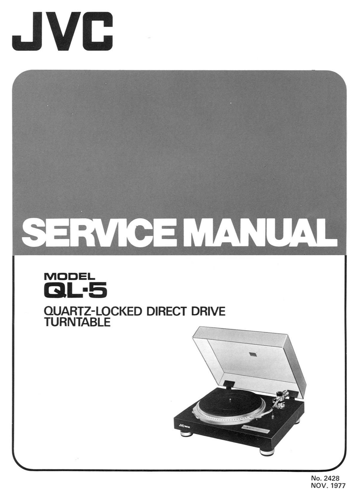
Jvc QL 5 Service Manual

This is the 25 pages manual for Jvc QL 5 Service Manual.
Read or download the pdf for free. If you want to contribute, please mail your pdfs to info@audioservicemanuals.com.

Page: 1 / 25
left right
Jvc QL 5 Service Manual

Extracted text from Jvc QL 5 Service Manual (Ocr-read)


Page 2

Contents

Page
1. Specifications ........................................................ 2
2. Service Precautions ..................................................... 3
3. Features ............................................................ 3
4. "How to Operate" (Names & Functions) ....................................... 3
5. Block Diagrams
5-(1) Servomotor Control System ........................................ 4
5-(2) ICBOZ Integrated Circuits and Waveforms .............................. 5
6. Troubleshooting
6-(1) Platter does not rotate ............................................ 5
6-(2) Platter rotates at a high speed ....................................... 5
6-(3) Rotation is not locked to the crystal oscillator frequency ..................... 7
7. Parts Replacement
7-(1) Stylus Replacement .............................................. 8
7-(2) Cartridge Replacement ............................................ 8
8. Adjustment Procedures
Servomotor Control Section
8-(1) Power Supply Voltage Check ....................................... 9
8-(2) Lock Adjustment ............................................... g
8-(3) Brake Mechanism Adjustment ....................................... 10
Tonearm Section
8-(4l Tonearm Height Adjustment ........................................ 11
8-(5) Arm Lifter Height Adjustment ....................................... 11
8-(6) Overhang Adjustment ............................................ 11
8-(7) Headshell Angle Adjustment ........................................ 11
848) Tracking Force Adjustment ........................................ 12
8-9) Anti-skating Adjustment .......................................... 12
8-(10) Arm-rest Height Ajustment ......................................... 12
9. Lubrication .......................................................... 13
10. Exploded Views and Parts List
10-(1) Servomotor Control and Cabinet Ass'y ................................. 13
10-(2) Parts List with Specified Numbers for Designated Areas ...................... 15
10-(3) Tonearm Assy ................................................. 15
11. Printed Circuit Board Ass'y and Parts List
11-(1) TXX-101 Servomotor Control P.C. Board Ass'y ........................... 16
1-1-(2) TSC-80F (688) Power Supply P.C. Board Assy ........................... 21
12. Schematic Diagram ..................................................... 22
13. Packing Materials and Part Numbers .......................................... 24
14. Accessories List ....................................................... 24
CHECKING YOUR LINE VOLTAGE (For US. Military Market and Other Countries) @
Before inserting the power plug, please check this setting to see that it corresponds

with the line voltage in your area. If it doesnt, be sure to adjust the voltage selector
switch to the proper setting before operating this equipment. The voltage selector
switch is located either on the sets on the chassis. Simply insert a screw driver into the
voltage selector switch and turn it in either direction while pressing slightly and in such
a way that the desired voltage marked on the switch is positioned underneath the
arrow marked on the rear panel or the chassis. The voltage selector switch accom-
modates up to three turns in either direction.

OL-5
No. 2428