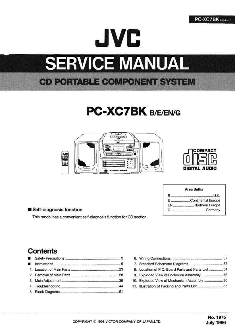
Jvc PCXC 7 BK Service Manual

This is the 110 pages manual for Jvc PCXC 7 BK Service Manual.
Read or download the pdf for free. If you want to contribute, please mail your pdfs to info@audioservicemanuals.com.

Page: 1 / 110
left right
Jvc PCXC 7 BK Service Manual

Extracted text from Jvc PCXC 7 BK Service Manual (Ocr-read)


Page 1

.Jvc
SERVICE MANUAL

PC-XC7BK B/E/EN/G

I Self-diagnosis function

Contents

FPS-0!"?

Safety Precautions ..................................

Instructions .................
Location of Main Parts
Removal of Main Parts
Main Adjustment ..
Troubleshooting
Block Diagrams ........................................................... 51

This model has a convenient self-diagnosis function for CD section.

FOWNS

. Illustration of Packing and Parts List .......

@figfi

DIGITAL AUDIO

Area Suffix

...................... U.K.
Continental Europe
....... Northern Europe
G .................................. Germany

Wiring Connections .................................
Standard Schematic Diagrams ............
Location of P.C. Board Parts and Parts List .
Exploded View of Enclosure Assembly
Exploded View of Mechanism Assembly


COPYRIGHT © 1996 VICTOR COMPANY OF JAPAN,LTD.

No. 1975
July 1996

Page 2

xc7B/E/ENIG

1. Safety Precautions

1. The design this product contains special hardware and many circuits and components specially for safety purposes. For continued
protection. no changes should be made to the original design unless authorized in writing by the manufacturer. Replacement parts
must be identical to those used in the original'circuits. Service should be performed by qualified personnel only.

2. Alterations of the design or circuitry of the product should not be made. Any design alterations of the product should not be made.
Any design alterations or additions will void the manufactures warranty and will further relieve the manufacture of responsibility
for personal iniury or property damage resulting therefrom.

3. Many electrical and mechanical parts in the product have special safety - related characteristics. These characteristits are often
not evident from visual inspection nor can the protection afforded by them necessarily be obtained by using replacement
components rated for higher voltage. wattage, etc. Replacement perm which have these special safety characteristics are
identified in the parts list of service manual. Electrical components having such features are identified by shadingufjl) and ( A)
on the schematic diagram and parts list in the service manual, The use of a substitute replacement which does not have the same
safety characteristics as the recommended replacement part shown in the parts list of service manual may create shock. fire. or
other hazards.

4. The leads in the products are routed and dressed with ties. clamps , tubings. barriers and the like to be separated from live parts,
high temperature parts. mpving parts and or sharp edges for the prevention of electric shock and fire hazard. When service is
required. the original lead routing and dress should be observed. and it should be confirmed that they have been returned to
normal. after reassembling.

5. Leakage current check (Electrical shock hazard testing)

After re - assembling the product, always perform an isolation check on the exposed metal parts of the product (antenna

terminals. knobs. metal cabinet. screw heads. headphone jack, control shafts. etc.) to be sure the product is safe to operate

without danger of electrical shock. Do not use a line isolation

AC VOLTMETER
transformer during this check. m (Having 1000 ohms/volt,

- Plug the AC line cord directly into the AC outlet. using a"Leakage or more nmw'w)
current tester". measure the leakage current from each exposed ;T

0.15 11F AC TYPE

m tl rt fthe b , nicula sed m tal rt
ea pa 0 ca met pa ry any expo e pa 1

having a return path to the chassis. to a known good earth ground. pi, mi, prob:

v- on each exposed
1500 n. 10 W metal part.

Any leakage current must not exposeed 0.5mA AC(r.m.s.) l
- Alternate check method
Plug the AC line cord directly into the AC outlet. Use an AC Good earth ground
voltmeter having 1,000 ohms per volt or more sensitivity in the following manner. Connect a 1,500 ohms 10W resistor paralleled
by a 0.15 [1 F AC type capacitor between an exposed metal part and a known good earth ground, Measure the AC voltage
across the resistor with the AC voltmeter. Move the resistor connection to each exposed metal part. particularly any exposed
metal part having a return path to the chassis, and measure the AC voltage across the resistor. Now. reverse the plug in the AC
outlet and repeat each measurement, Any voltage measured must not exceed 0.75V AC(r.m.s,).This corresponds to 0.5mA
AC(r.m.s.).

warni ng (UK ONLY)

1. This equipment has been designed and manufactured to meet international safety standards.

2. It is the legal responsibility of the repairer to ensure that these safety standards are maintaintaind.
3. Repairs must be made in accordance with the relevant safety standards.

4. It is essential that safety critical components are replaced by approved parts.

5. if mains voltage selector is provided, check setting for local voltage.

2 (N0. 1975)

Page 30

-XC7e/E/aue

9 Main board assy and cassette mechanism assy
(Fig. EA 6~Fig. 2-7)

1 . Remove the front cabinet. Speak 3mm

2. Remove the cassette mechanism assembly and main
board assembly unit from the rear cabinet.

3. Turn the unit upside down so that the top cabinet faces
down.

4. Remove the five screws ® retaining the main board assy.

5. Slightly lift the main PC board, then disconnect the parallel
wires coming from the switch PC board assembly from
CN701 on the main PC board assembly.

6. Turn the main PC board assembly upside down (the parts
side will face up). Disconnect the wire holder PP11 on the

Top cabinet
PC board, then disconnect the A mechanism head wire
CNA32 (5 pins), the B mechanism head wire CNA31 (3

pins), and the mechanism drive connector CNASS (15 wires should have been
pins). Tightend together with bundled with a wire holder.
, , 4 m d '

7. Remove the three screws ® retaining the swttch board 89'8" we

ass'y. (When removing the switch PC board holder with the

switch PC board mounted on it, remove the two screws 3?: 7

A

) _ . l4 , 9 l4
8. Remove the five screws ® retaining the mechanism.
9. Open the cassette door, then remove the cassette 0

thin studs

mechanism unit from the top cabinet.

O Removing the cassette door (Fig. 248) j \
a. Remove the cassette mechanism assy. push the cassette I3 @ I3
door left arm inward, disengage the door shaft and remove

\\<
it

S . . Terminal side
it from the top cabinet. Make sure to hold the edge while WM board assy Pull out the wire

performing this step or the door spring may fly out, Fig.2-7 wee"memi"sds
possibly causing injury.

b. When reattaching. start with the door spring side, then Fitthedoorspringintoheslit

Remove the door shaft

push the opposite side in.

c. Fit the door spring into the slit.

(We Although cassette door removal is possible with the
mechanism assembly mounted, removing the mechanism
assembly beforehand will make it easier and ensure

correctness.)

h ( Remove the door shaft by
Door damper gear PUSNHQ the holder arm in
the direction of the arrow.

Fig. 2 - 8

30 (No. 1975)

Page 39

El Main Adjustment

I Test Instruments reqlred for adjustment
1 . Low frequency oscillator
(oscillation frequency: 50Hz to 20kHz)
(Output: 0 st with 60 Q terminator)
2. Attenuator( Impedance : 600 Q )
3. Test Tapes

VI I712 (V 712) ------------- For tape speed,wow and
flutter measurement
VI I724 (V 724) ------------ For play back output level

V1173!) (VT739) - For playback frequency
response check
VTT703 (VT703) ----- For head azimuth measurement
4 Electronic voltmeter, Distortion meter
5. Resistor...600 Q for attenuator matching
6. Torque gauge ----------- Cassette type for CTG - N
mechanism adjustment
7. Wow and Flutter meter , Frequency counter
8. Blank tape ------------- Normal:UR.Chrome: A0225
I Measuring conditions (Amplifier section)
Supply voltage .................... ........ 230V (50/60HZ)
Reference output : Speaker ------- o st (0.775W / 3 S2
(Volume Level: 19)
: Headphone ' - 10 st (0.245V)/ 32 Q

0 Standard position of functionswitches

Function switch ....................................... TAPE
Mode switch ....................................... STEREO
0 Standard position of volume control

Sound ........................................... Flat position

AHB PRO ................................................ OFF

Main volume adjust --------- 0 st Speaker out(Vo|.19)
Headphone out(VoI.20)

Beat Cut Switch .......................................... CU

Standard ms! frequency ..................... . ........ 1 kHz

; unless otherwise specified.

Reference input level ------- . ----- TP(CN301) : - 20st

Input for REC/PB, Check &measuring ----------- CN301
: -20 st

0 Test remarks

1. Negative side of the input and output on the testing
set. that ought to be separately to each other. and
then bear in mind there connection the testing set with
2 channeles Electronic voltmeter. the negative side
never connect commonly.

2. Replaced output load with a dummy and that lead
wire to be used as big as posible.

3. Attach top cover when measuring and connect filter

shown below Fig. 1 to V. meter.

I Measuring condition (Radio section)

Refer to rating source ----------------- Tuner+B : DC 5.7V
Reference output '''''' Speaker: 20mW(0.245 V) / 3 Q

Headphone : 011 mW (0.06 W32 9
AM frequency --------------------- 400Hz modulation 30%
FM frequency ........................... 400HZ modulation

frequency deviation 22.5kHz
0 Standard position of switches and controllers
Funcfion ............................................ RADIO
Mode .......................................... STEREO
O Caretul points for adjustment
1. Connect 30 pF capacitor and 33 k S? resistor to the
output side of the IF sweeper 'm series while 0.082 11
F capacitor and 100k 9 resistor to the input side in
series.
2.Set output level of the lF sweeper as minimum as
adjustable.
3. RF Alignment order
Procedure of the steps of tracking should be kept.

©Test point : CN301( Top vlew )

BIAS
GND

Fig.3-1

(No. 1975) 39

Page 50

Pc-xc7B/EIEN/G

I Tracking section

Does a tracking error signal
appear at TP503 when the disc

W----I- 0.4V

N Check the circuitry in the vicinity OK
0HC501®~© and @~@

V

The pickup or ic501 is defective.

{r

starts to rotate?

{7

Check the oflset oi the tracking NG
error of TPSOS.

____1__

is TP504's waveform oi the
tracking Ioop ON?

V

Adjust VR501.

' Check the circuitry in the
IP503 W N vicinity of |0501 @ ~ @ and 0K ICBO1 is defective.
: |0601 @ ~ QB .
TP504 -fv«~-- ____-_

i

J.

Is the lens moved vertically when
the team ® and 63 are N Is 0.4V produced when CN501 N

shortcircuited" Q} and ® are short-circuited?

Check the circuitry in the
vicinity of I0502 Q) ~ ®
and ICSO1 ® ~ :3.

J, i Y , i

ICGOt is defective. Check the pickup and l0502 or ICSO1 is defective. I
connections.

Fig. 4-13

V

50 (No 1975)