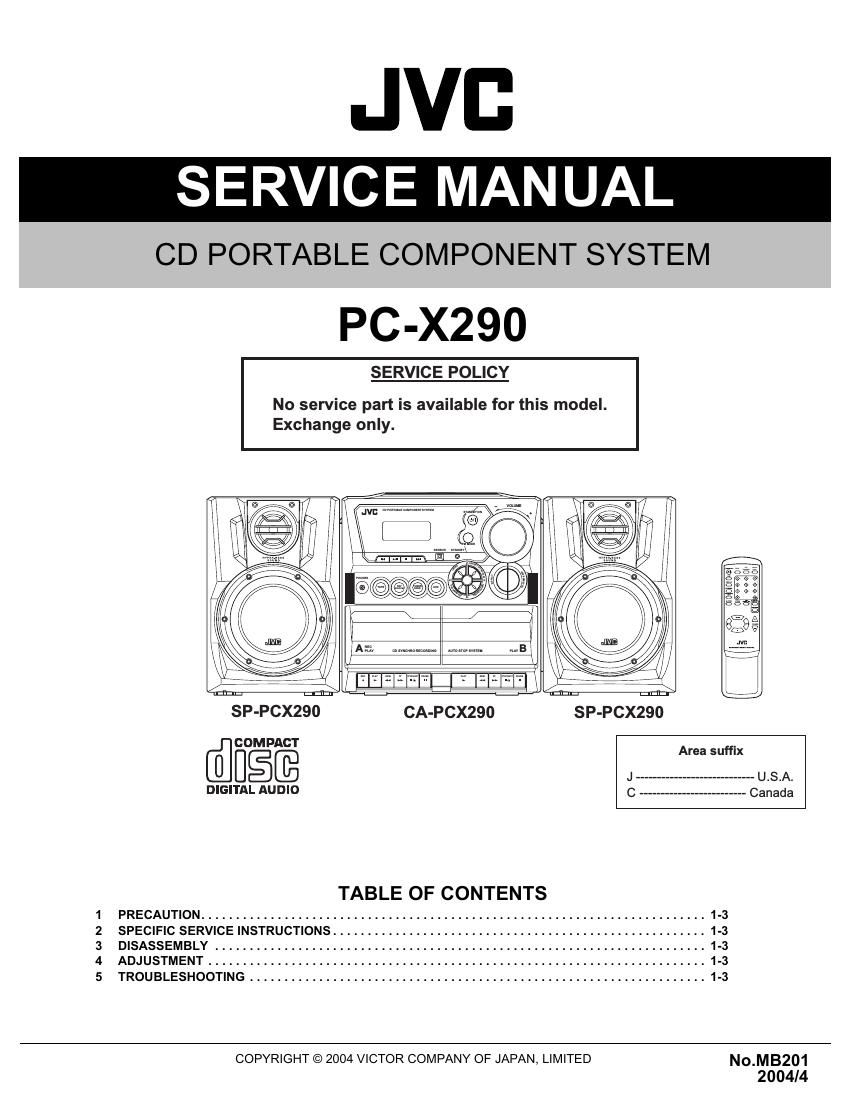
Jvc PCX 290 Service Manual

This is the 83 pages manual for Jvc PCX 290 Service Manual.
Read or download the pdf for free. If you want to contribute, please mail your pdfs to info@audioservicemanuals.com.

Page: 1 / 83
left right
Jvc PCX 290 Service Manual

Extracted text from Jvc PCX 290 Service Manual (Ocr-read)


Page 1

1-2 (No.MB201) SPECIFICATION Designs and specifications are subject to change without notice. Amplifier Output Power 5 W per channel, min. RMS, driven into 3.2 -„¦ at 1 kHz with no more than 10% total harmonic distortion. Audio input sensitivity/Impedance (at 1 kHz) AUX:1 000 mV/47 k-„¦ Speakers/Impedance 3.2 -„¦ - 8 -„¦ Tuner FM tuning range 87.5 MHz - 108.0 MHz AM tuning range 530 kHz - 1 710 kHz CD player CD Capacity 1 CD Dynamic range 60 dB Signal-to-noise ratio 75 dB Cassette deck Frequency response Normal (type I) 50 Hz - 10 000 Hz Wow and flutter: 0.15% (WRMS) General Power requirements AC 120 V , 60 Hz DC 12 V ("R20(SUM-1)/D(13D)" batteries (8)) Power consumption 20 W (at operation) 3 W (on standby) Dimensions (approx.) 270 mm × 274 mm × 298 mm (W/H/D) (10 11/16 in. × 10 3/4 in. × 11 3/4 in.) Mass (approx.) 4.1 kg (9.1 lbs) Speaker Type 2-way bass-reflex type Speaker units Woofer: 10 cm (4 in.) cone × 1 Tweeter: 5 cm (2 in.) cone × 1 Power handling capacity 5 W Impedance 3.2 -„¦ Frequency range 50 Hz - 18 000 Hz Dimensions (approx.) 180 mm × 270 mm × 228 mm (W/H/D) (7 1/8 in. × 10 3/4 in. × 9 in.) Mass (approx.) 1.7 kg (3.8 lbs) each

Page 2

(No.MB201)1-3 SECTION 1 PRECAUTION This service manual does not describe PRECAUTION. SECTION 2 SPECIFIC SERVICE INSTRUCTIONS This service manual does not describe SPECIFIC SERVICE INSTRUCTIONS. SECTION 3 DISASSEMBLY This service manual does not describe DISASSEMBLY. SECTION 4 ADJUSTMENT This service manual does not describe ADJUSTMENT. SECTION 5 TROUBLESHOOTING This service manual does not describe TROUBLESHOOTING.

Page 43

1-10 (No.MB200) 3.2.5 Removing the cassette mechanism assembly (See Fig.22 to24) (1) Push the two eject button on the front side to open the cas- sette door. (2) Disconnect the wire from connector CN201 , CN202 and CN203 on the main board. (3) Remove the six screws N attaching the cassette mecha- nism assembly. Fig.22 Fig.23 Fig.24 Cassette door Eject button CN203 CN202 CN201 Main boardh Cassette mechanism assembly N N

Page 59

¦ Enclosure components parts listParts NumberParts nameQTYRemarksRef. No.Suffix 36-00290-02LE030401 X290 CD Door1New Spring59 11-00290-17PC-X290 CD Gear PCB194HB 1.6mm60 63-00303-81LE030401 E303 Damper Gear1B30B (1x CD Door)61 78-00612-00Terminal 212A162 48-07930-80LE030401 PU Cover 1TCP-110P (Thomson CD)63 35-00003-80LE030401 E Ring M311x Push Rod64 98-00010-80LE030401 CD Pick Up1TCP11TK2PX (Thomson)65 81-02750-80LE030401 CD Damper23140-114-1389-266 81-02750-81LE030401 CD Damper23140-114-1390-267 03-08229-80Lead Free IC TA8229K1Toshiba68 39-00290-05LE030401 X290 Heat Sink1T=3.0mm69 01-01375-80Lead Free TR. 2SB1375170 12-00006-80Lead Free Spk. Terminal1WP-4112AE (050)71 11-00290-11PC-X290 Main PCB194VO 1.6mm72 12-00214-80Lead Free RCA Jack1RCA-214 2 Chanel73 16-10202-801Lead Free Slide Switch12P2T SK22D06G474 42-00290-06LE030401 X290 Beat Switch1PC Plate75 48-00290-11LE030401 X290 Main PCB/CD Tray1BKT. (ABS)76 55-09010-80LE030401 Plastic Cover1W/O Felt77 43-00290-00LE030401 X290 CD Door Lens1PMMA78 97-09019-80LE030401 OP192 Magnet12049583079 39-04200-80LE030401 UMS4200 Metal Cover180 66-00290-00LE030401 X290 CD Door1ABS81 57-00290-00LE030401 X290 Handle1ABS82 61-00290-03LE030401 X290 Rear Cabinet ( J )1Hips (94V2)83 48-00290-07LE030401 X290 handle Lock1BKT. L (ABS)84 48-00290-08LE030401 X290 handle Lock1BKT. R (ABS)85 12-00004-33LE030401 AC Power Socket 1PSP27 (UL)86 12-00004-33LE030401 AC Power Socket 1PSP27 (UL)87 35-40008-80LE030401 M4 Nut289 35-30009-80LE030401 Spring Washer2 M4 (f4 x f7 x 1mm)90 35-00008-80LE030401 Metal Washer2 f9 x f4 x 0.8mm91 15-00290-00LE030401 X'Former1T06821A 120V (UL)92 39-00290-03LE030401 X290 X'Former1Metal Plate93 11-00290-03PC-X290 Power PCB194VO 1.6mm94 39-09025-84LE030401 OP251 Heat Sink 1JiangSu95 03-07805-08IC L7805CV1Array96 74-00290-05LE030401 X290 Battery Spring ( - )197 74-00290-04LE030401 X290 Battery Spring ( + )198 74-00150-81LE030401 X150 Battery Spring (+,-)399 Battery8100 58-00290-00LE030401 X290 Battery Door1ABS101 87-00290-04LE030401 X290 Rating Label ( J )1102 39-00290-00LE030401 X290 Ant Contact Plate1T=0.5mm103 23-00290-00LE030401 X290 Rod Antenna1NC-9601-593104 40-03008-11Screw M3 x 8 1BH/MS105 40-13021-01Screw M3 x 215BH/ST106 40-13010-02Screw M3 x 102KH/ST 107 40-12608-11 Screw f 2.6 x 815BH/ST108 40-13010-01 Screw f 3 x 10¹²BH/ST109 40-13012-03 Screw f 3 x 124WH/ST110 40-04010-03BScrew M3 x 8 2WH/MX "Ni"111 40-13008-41 Screw f 3 x 83BH/ST Zn112 40-12608-01Screw M2.6 x 84BH/MS Zn113 40-12608-03 Screw f 2.6 x 83WH/ST Zn114 40-12606-01 Screw f 2.6 x 611BH/ST Zn115 40-13008-11 Screw f 3 x 87BH/ST Zn116 40-12610-01 Screw f 2.6 x 10¹⁰BH/ST Zn117 40-13012-01 Screw f 3 x 122BH/ST Zn118 40-02005-90 Screw f 2 x 53"Tap" 10462020119 40-52610-03 Screw f2.6 x 104 CD Damper WH (f11.5)120 40-02045-90 Screw f 2 x 4.511052855121 38PC-X290

Page 71

PC-X290¦ Electrical parts list (Display & Key board)Parts NumberParts nameQTYRemarksRef. No.Suffix20-21100-8010Pin Header1Lead Free wire P=2mm R-Angle JSTCN601 20-41102-8010Pin Hou'G1Lead Free Cable UL2651#28 P=2 220/4CN606 to CN601 25-84050-82Rainbow Cable1Lead Free #28UL 2P 4/50/4CN608 to CN602 BT-302Led1Lead Free 02-30005-84 YEK-31-589ED601 BT-302Led1Lead Free 02-30005-84 YEK-31-589ED602 BT-302Led1Lead Free 02-30005-84 YEK-31-589ED603 BT-302Led1Lead Free 02-30005-84 YEK-31-589ED604 ELT-3142DLed1Lead Free 02-30022-82 f3mm (Elstar)D605 08-04344-50Ferrite Core1T25 x 15 x 10For CN601 Wire 91-00290-00LCD Display1Lead Free PC-X290 LCD DisplayLCD601 11-00290-01PC-X2901Display PCB 94HB 1.6mmPCB 11-00290-02PC-X2901Key PCB W/07/10/13/17 94HB 1.6mmPCB 07-74152-50TCarbon Resistor1Lead Free 1.5K 1/8W ±5% 52mm T.T.R601 07-74202-50TCarbon Resistor1Lead Free 2K 1/8W ±5% 52mm T.T.R602 07-74272-50TCarbon Resistor1Lead Free 2.7K 1/8W ±5% 52mm T.T.R603 07-74392-50TCarbon Resistor1Lead Free 3.9K 1/8W ±5% 52mm T.T.R604 07-74152-50TCarbon Resistor1Lead Free 1.5K 1/8W ±5% 52mm T.T.R605 07-74202-50TCarbon Resistor1Lead Free 2K 1/8W ±5% 52mm T.T.R606 07-74272-50TCarbon Resistor1Lead Free 2.7K 1/8W ±5% 52mm T.T.R607 07-74152-50TCarbon Resistor1Lead Free 1.5K 1/8W ±5% 52mm T.T.R608 07-74202-50TCarbon Resistor1Lead Free 2K 1/8W ±5% 52mm T.T.R609 07-74272-50TCarbon Resistor1Lead Free 2.7K 1/8W ±5% 52mm T.T.R610 07-74392-50TCarbon Resistor1Lead Free 3.9K 1/8W ±5% 52mm T.T.R611 07-74682-50TCarbon Resistor1Lead Free 6.8K 1/8W ±5% 52mm T.T.R612 07-74153-50TCarbon Resistor1Lead Free 15K 1/8W ±5% 52mm T.T.R613 07-74122-50TCarbon Resistor1Lead Free 1.2K 1/8W ±5% 52mm T.T.R614 07-74122-50TCarbon Resistor1Lead Free 1.2K 1/8W ±5% 52mm T.T.R615 07-74151-50TCarbon Resistor1Lead Free 150 1/8W ±5% 52mm T.T.R617 07-74151-50TCarbon Resistor1Lead Free 150 1/8W ±5% 52mm T.T.R618 07-74470-50TCarbon Resistor1Lead Free 47 1/8W ±5% 52mm T.T.R619 RPM7138-V4Sensor1Lead Free 02-67138-80 RohmREM601 16-10101-80Tact SW1Lead Free EVQJAE 05R H=5mmSW601 16-10101-80Tact SW1Lead Free EVQJAE 05R H=5mmSW602 16-10101-80Tact SW1Lead Free EVQJAE 05R H=5mmSW603 16-10101-80Tact SW1Lead Free EVQJAE 05R H=5mmSW604 16-10101-80Tact SW1Lead Free EVQJAE 05R H=5mmSW605 16-10101-80Tact SW1Lead Free EVQJAE 05R H=5mmSW606 16-10101-80Tact SW1Lead Free EVQJAE 05R H=5mmSW607 16-10101-80Tact SW1Lead Free EVQJAE 05R H=5mmSW608 16-10101-80Tact SW1Lead Free EVQJAE 05R H=5mmSW609 16-10101-80Tact SW1Lead Free EVQJAE 05R H=5mmSW610 16-10101-80Tact SW1Lead Free EVQJAE 05R H=5mmSW611 16-10101-80Tact SW1Lead Free EVQJAE 05R H=5mmSW612 16-10101-80Tact SW1Lead Free EVQJAE 05R H=5mmSW613 16-10101-80Tact SW1Lead Free EVQJAE 05R H=5mmSW614 16-10101-80Tact SW1Lead Free EVQJAE 05R H=5mmSW615 16-10101-80Tact SW1Lead Free EVQJAE 05R H=5mmSW616 18-92040-86Encoder1Lead Free Vol. EC162102 FIB-HA1-24VR601 84-00005-80Cable Tie1LE030401 6.5" UL50

Page 73

1.Terminal layout 2.Block diagram 3.Pin function TC9257F(IC102):PLL for DTS 1.Terminal layout 2.Block diagram 3.Pin function 1 2 3 4 5 6 7 8 9 10 20 19 1817 16 15 14 1312 11 1/2 2 MODULUS PRESCALER 4 bit SWALLOW COUNTER POWER ONRESET 12bit PROGRAMMABLE COUNTER OSC CIRCUIT REFERENCE COUNTER MAX. 24bit REGISTER 24 bit SHIFT REGISTER ADDRESS DECODER UNLOCK 24 BIT REGISTER RESET FM H HF FM MODELF 1ms OSC 412 154 OT4 8 TEST 24225 10 4 4 OT-4 XT 1ms GATE AMPAMP 5 PHASE COMPARATOR TRI-STATE BUFFER TRI-STATE BUFFER DO1 DO2 (DO2/OT-4) I/O-5/CLK I/O PORT I/O-6 I/O-9/IF IN2 I/O-8/IF IN1 ( I/O-5/IF IN1) I/O-7/SC IN OT-1 OT-3 OT-2 OT-4 GND VDD PSC AMP OUTPUT PORT20bit BINARY COUNTER UNIVERSAL COUNTER CONTROL FMIN AMIN XT XT XT DATA CLOCK PERIOD Pin No. Symbol I/O Function 1 XT - Crystal oscillator pins 2 XT - Crystal oscillator pins 3 PERIOD I Period signal input 4 CLOCK I Clock signal input 5 DATA I/O Serial data input/output 6 OT-1 O General-purpose output ports 7 OT-2 O General-purpose output ports 8 OT-3 O General-purpose output ports 9 OT-4 O General-purpose output ports 10 I/O-5/CLK I/O General-purpose I/O ports 11 I/O-6 I/O General-purpose I/O ports 12 V DD - Power supply pins 13 AM IN I Programmable counter input 14 FM IN I Programmable counter input 15 GND - Power supply pins 16 I/O-9/IF IN2 I/O General-purpose I/O Ports/ 17 I/O-8/IF IN1 I/O General-purpose counter frequency measurement input General-purpose I/O ports/ General-purpose counter cycle measurement input 19 DO1 O Phase comparator output 20 DO2 O Phase comparator output 18 I/O-7/SC IN I/O 52 PCX290