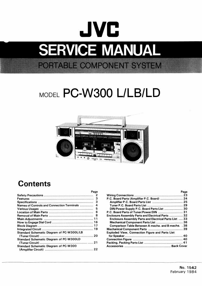
Jvc PCW 300 LD Service Manual

This is the 42 pages manual for Jvc PCW 300 LD Service Manual.
Read or download the pdf for free. If you want to contribute, please mail your pdfs to info@audioservicemanuals.com.

Page: 1 / 42
left right
Jvc PCW 300 LD Service Manual

Extracted text from Jvc PCW 300 LD Service Manual (Ocr-read)


Page 1

JVC
SERVICE MANUAL

MODEL PC-WSOO L/LB/LD

Contents

Safety Precautions ..
Features
Specifications ...........................................
Names of Controls and Connection Terminals .
Various Usages ...........
Location of Main Parts ..
Removal of Main Parts ..
Main Adjustments
How to Engage Dial Cord


Block Diagram ................ ..
Integrated Circuit ................................................... 19
Standard Schematic Diagram of PC-W300L/LB

(Tuner Circuit) ..................................................... 20
Standard Schematic Diagram of PC-WSOOLD

(Tuner Circuit) .................................................... 21
Standard Schematic Diagram of PC»W300

(Amplifier Circuit) ................................................ 22


Wiring Connections ...........................
P.C. Board Parts (Amplifier P.C. Board) .
Amplifier P.C. Board Parts List .
Tuner P.C. Board Parts List ......
DIN/Power Supply P.C. Board Parts List
P.C. Board Parts of Tuner/PowerlDlN ........

Enclosure Assembly Parts and Electrical Parts ........... 32
Enclosure Assembly Parts and Electrical Parts List
Mechanical Component Parts List ........................ 36
Comparison Table Between A mecha. and B mecha. . 38

Mechanical Component Parts .................................. 39

Exploded View, Connection Figure and Parts List

for Speaker .........

Connection Figure .
Packing. Packing Parts Is .
Accessories ....................

No. 1542
February 1984

Page 2

PC

2

Safety Precautions

l. The design of this product contains special hardware.

Many circuits and components specially for safety
purposes.
For continued protection, no changes should be made to
the original design unless authorized in writing by the
manufacturer. Replacement parts must be identical to
those used in the original circuits. Service should be per-
formed by qualified personnel only.

2. Alterations of the design or circuitry of the product

should not be made. Any design alterations or additions
will void the manufacturers warranty and will further
relieve the manufacturer of responsibility for personal in-
jury or prOperty damage resulting therefrom.

3. Many electrical and mechanical parts in the product

have special safety-related characteristics. These
characteristics are often not evident from visual inspec-
tion nor can the protection afforded by them necessarily
be obtained by using replacement components rated for
higher voltage, wattage, etc. Replacement parts which
have these special safety characteristics are identified in
the parts list of Service manual. Electrical components
having such features are identified by ( A ) on the
schematics and parts list in Service manual. The use of a
substitute replacement which does not have the same
safety characteristics as the recommended replacement
part shown in the parts list in Service manual may create
shock, fire, or other hazards.

4. The leads in the products are routed and dressed with

ties, clamps, tubings, barriers and/or the like to be
separated from live parts, high temperature part, mov-
ing parts and/or sharp edges for the prevention of elec
tric shock and fire hazard.

When service is required, the original lead routing and
dress should be observed, and they should be confirmed
to be returned to normal, after re-assembling.

Power switch A'ssy

V. select switch
AC IN jack
DC jack

Fuse

DIN P.C. Board Ass'y

Power supply P.C. Board Assv
Power transformer

(N0. 1542)

5. Leakage current check

(Safety for electrical shock hazard)

After re-assembling the product, always perform an

isolation check on the exposed metal parts of the Pro-

ducts (antenna terminals, knobs, metal cabinet, screw

heads, earphone jack, control shafts, etc.) to be sure the

product is safe to operate without danger of electrical

shock.

Do not use a line isolation transformer during this check.

I Plug the AC line cord directly into the AC outlet. Us-
ing a Leakage Current Tester, measure the leakage
current from each exposed metal part of the cabinet,
particularly any exposed metal part having a return
path to the chassis, to a known good earth ground
(water pipe, etc.l. Any leakage current must not ex-
ceed 0.5 mA AC (r.m.s.l.

O Alternate check method.
Plug the AC line cord directly into the AC outlet. Use
an AC voltmeter having 1,000 ohms per volt or more
sensitivity in the following manner. Connect a
1500 (2 10 W resistor paralleled by a 0.15 [LF AC-
type capacitor between an exposed metal part and a
known good earth ground (water pipe, etc.).
Measure the AC voltage across the resistor with the
AC voltmeter.
Move the resistor connection to each exposed metal
part, particularly any exposed metal part having a
return path to the chassis, and measure the AC
voltage across the resistor. Now, reverse the plug in
the AC outlet and repeat each measurement. Any
voltage measured must not exceed 0.75 V AC
(r.m.s).
This corresponds to 0.5 mA AC (r.m.s).

AC VOLTMETER
CD (HAVING 1000 mv.

OR MORE SENSITIVITY)
-o o~

0.15 itF ACVTYPE

*l i-
D
1500 [Z 10 W PLACE THIS PROBE
ON EACH EXPOSED

GOOD EARTH GROUND METAL PART

Page 10

PC-W300 L/LB/LD

11. A and B mechanisms

Remove the three screws and @ .

Mechanism Parts

1. Flywheel and belt
1)Remove two screws fastening the F.R.
bracket, and remove the main belt.
2) Pull out the flywheel with the reel drive belt.

2. Reel assembly unit
Remove 4 screws ® fastening the reel assy unit.

3. Motor
1) Remove two screws fastening the motor from the
F.R. bracket.
2) Pull out the motor pulley from the motor shaft.

4. Reel feather
Pull out the reel feather from the shaft.

5. Rec/PB head and Erase head
1 l Remove two screws © fastening the button
frame assy.
2) Remove two screws © fastening the head assy
with the head block.

Fig. 22
10 (No. 1542)

Page 15

PC-W3OO L/LB/LD

Item

Description

3. AM RF ALIGNMENT

3-1 Conditions of the receiver.
(1) Power source: Same as mentioned in item 1-1.
(2) Function switch position: RADIO
(3) Volume control: 50 mW
(4) Tone control: Center (Bass, Treble) position
(5) Variable capacitor: Refer the following list shown in item 34.
3-2 Conditions of SSG.
(1) Modulation: Refer the basic condition
(2) Frequency: Refer the following list shown in item 3-4.
(3) Output level of the attenuator in SSG: Approx. 50 mW
33 Power output measuring position: Speaker terminals
3-4 Alignment:
Band Select Sort of Antenna to be . . . . Aligning
Switch Position attache d to 556 Frequency of $56 Variable Capacitor Posmon Position
1 520 kHz Max. capacity L4
2 1,650 kHz Min. capacity T03
3 MW Loop Antenna Ajust the above aligning position (L4 & T03) repeatedly so that
the tuner can be received above frequency range (band Width).
4 620 kHz to be received 620 kHz L3
1,400 kHz to he received 1,400 kHz TC-6
6 Adjust the above aligning position (L3 & TC-6) repeatedly so
that the tuner can be obtained the best sensitivity.
145 kHz Max. capacity L5
360 kHz Min. capacity TC-4
Adjust the above aligning position (L5 & TC-4) repeatedly so
9 LW Loop Antenna that the tuner can be received above frequency range (band
width)
10 160 kHz to be received 160 kHz L7
1 1 350 kHz to be received 350 kHz TC-7
12 Adjust the above aligning position (L7 & TC-7) repeatedly so
that the tuner can be obtained the best sensitivity.
13 5.8 MHz Max. capacity L6
14 18.6 MHz Min. capacity TC-5
D mm Adjust the above aligning position (L6 & TC-5) repeatedly so
1 5 SW u y that the tuner can be received above frequency range (band
Antenna .
Width).
16 6.0 MHz to be received 6.0 MHz L8
17 18.0 MHz to be received 18.0 MHz TC-B
1 8 Adjust the above aligning position (L8 & TC-8) repeatedly so
that the tuner can be obtained the best sensitivity.

(No. 1 542)

15

Page 42

Accessories

A parts are safety assurance parts.
When replacing those parts, make sure to use the specified one.

A Pan No. Parts Name Remarks O'ty
VNM0939-301 Instruction Book 1

A QMP3950-183 Power Cord PC-W3OOL/LD 1

A OMP901 7-00983 " PC-WSOOLB 1
VMP0035-001 Speaker Cord 2
BTZOOSO Guarantee Certificate PC-W300LB 1
BT20066 PC-WSOOLB/LD 1
OZL1002-003 Warranty Lavel PC-W3OLB 1
31465-18 Mark PC-W3OOLB 1
VJH3019-00H Handle Ass'y 1
VNFOI 60-001 Featur Sticker Left 1
VNFO160-002 " Right 1
BT20065 Warranty Card PC-W300LD 1
BT20054-003A Caution Sheet PC-W3OOLD 1

VICTOR COMPANV OF JAPAN, LIMITED

RADIO & RECORDING MACHINE DIVISION 10-1, 1-chome, Ohwatari-cho, Maebashi-city, Japan

@ Printed in Japan
-5902 -0_