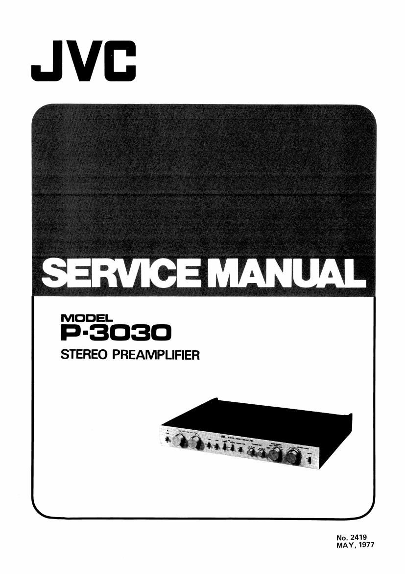
Jvc P 3030 Service Manual

This is the 32 pages manual for Jvc P 3030 Service Manual.
Read or download the pdf for free. If you want to contribute, please mail your pdfs to info@audioservicemanuals.com.

Page: 1 / 32
left right
Jvc P 3030 Service Manual

Extracted text from Jvc P 3030 Service Manual (Ocr-read)


Page 2

Contents

N99??Nr

10.
11.

12.
13.
14.
15.
16.

Page
Specifications ............ . ............................................ 2
Precautions in Servicing .................................................. 2
Connection Diagram .................................................... 3
How to Operate ....................................................... 4
Removal of Bottom Plate, Top Cover, Panels, and Knobs ............................ 6
Main Parts Location .................................................... 7
Exploded Views and Parts List
7-(1) Front Panel, Top Cover and Bottom Plate ............................... 8
7-(2) Rear Panel .................................................... 10
Adjustment Procedure ................................................... 11
Block Diagram ........................................................ 12
Wiring Diagram of P.C. Board Assy .......................................... 13
Printed Circuit Board Ass'y and Parts List
11-(1) TPS-77 Power Supply P.C. Board Ass'y ................................ 14
11-(2) TPS-83 AC Fuse P.C. Board Ass'y .................................... 16
11-(3) TPS-85 L.E.D. P.C. Board Ass'y ..................................... 16
11-(4) TAE-122 MC Head Amp. & Equalizer Amp. P.C. Board Ass'y ................. 17
11-(5) TAG-424 Tone Control Amp. P.C. Board Assy ........................... 21
11-(6) TAG-425 Tone Control P.C. Board Assy ............................... 24
11-(7) TAO-436 Cartridge Load Switch P.C. Board Ass'y ......................... 25
11-(8) TAG-437 Muting P.C. Board Ass'y ................................... 26
Accessories List ....................................................... 26
Packing Materials and Part Numbers .......................................... 27
Transistor Lead Identification .............................................. 28
Parts List with Specified Number for Designated Areas ............................. 28
Schematic Diagram ..................................................... 29

P-3030
No. 2419

Page 3

1. Specifications

Transistor & Diode
Input Terminal and Input Impedance

Cartridge Load Select

Phono Overload

Output Terminal and Output Impedance :

Total Harmonic Distortion
(20 Hz - 20 kHz)

Frequency Response

Tone Control
Signal-to-Noise Ratio
at rated output (IHF A network)

Subsonic Filter

26 FETs, 41 Transistors & 19 Diodes
PHONO-l , 2 (Moving Magnet Type)
2 mV/100 SI, 33 k9, 47 kSZ, 100 kD.
PHONO»3 (Moving Coil Type)
0.1 mV/30 SI
TUNER, AUX, TAPE PLAY 1, 2
140 mV/more than 50 k9
(C) 100 pF, 220 pF, 330 pF, 470 pF
(R) 100 Q, 33 k9, 47 kSZ, 100 k0
PHONO-1, 2 (Moving Magnet Type)
300 mV (RMS) 1 kHz Before clip
PHONO-3 (Moving Coil Type)

15 mV (RMS) 1 kHz Before clip
TAPE REC 1,2 140 mV
OUTPUT 1, 2 1 V/BOO 9 (Rated output)

20 V (Max)

PHONO»1, 2 (Moving Magnet Type)

0.005 % or less (10 V)
PHONO-3 (Moving Coil Type)

0.05 % or less (1 V)
TUNER, AUX, TAPE PLAY 1. 2

0.005 % or less (10 V)
PHCNO-l,2 RIAA:0.3 dB (20 Hz-20 kHz)
PHONO-3 RIAA : 0.5 dB (30 Hz 7 20 kHz)
TUNER, AUX, TAPE PLAY 1, 2

10 Hz -40 kHz 1 0.5 dB
50 Hz (: 10 i 2 dB), 20 kHz (1 10 :2 dB)

PHONO-1, 2 76 dB

PHONO-3 66 dB

TUNER,AUX, TAPE PLAY 1, 2
96 dB

18 Hz 6 dB/Oct.

2. Precautions in Servicing

0 If a turntable equipped with MM cartridge is connected to the PHON0-3 terminals (for exclusive use with an MC
cartridge), most of high frequency sounds will be cut. The MC amplifier is overloaded, though the sound does not

seem distorted.

O The 100 (2 position is exclusively for a high output MC cartridge.
0 The cartridge load select switches are effective only for the PHONO-l and PHONO-2 terminals.

O If excessive hum is encountered during record playing, check for induction caused by the other components placed

around the preamplifier.

Employment of the preamplifier on top of a high power apparatus (like a power amplifier) will induce hum.
Keep it as far away from other apparatises as possible. Nearby appliances containing even small transformers may

cause induced hum if the transformers are imperfectly shielded.

P-3030
No. 2419